Saturday, August 31, 2013

Understanding the OSPF protocol

Small introduction to OSPF protocol

OSPF, or Open Shortest Path First, is a link-state, open-standard, dynamic routing protocol.  OSPF uses an algorithm known as SPF, or Dijkstra’s Shortest Path First, to compute internally the best path to any given route.OSPF is classless and converges fairly quickly, using cost as it’s metric.  A router running OSPF creates its own database which contains information on the entire OSPF network, not simply neighbor’s routes like EIGRP.  This allows the router to make intelligent choices about path selection on its own instead of relying exclusively on neighbor information.

OSPF routers do form neighbor relationships though.  They exchange hellos with neighboring routers and in the process learn their neighbor’s Router ID (RID) and cost.  Those values are then sent to the adjacency table. Every router is responsible for computing its own best paths to all destinations within an OSPF domain.  Once the SPF algorithm selects the best paths, they are then eligible to be added to the routing table. 
This protocol is considered as a Interior Gateway Protocol (simple IGP), which is widely used in ISP scenarios as an infrastructure protocol for BGP routing. 

Once a router has exchanged hellos with its neighbors and captured Router IDs and cost information, it begins sending LSAs, or Link State Advertisements.  LSAs contain the RID and costs to the router’s neighbors.  LSAs are shared with every other router in the OSPF domain.  A router stores all of its LSA information (including info it receives from incoming LSAs) in the Link State Database (LSDB).

OSPF is different from EIGRP in that it uses areas to segment routing domains.  This helps partition routers into manageable groups if the layer 3 network begins to get large. It all starts with area 0.  Every OSPF network must contain an area 0, sometimes referred to as the backbone area and every additional area must be physically connected to area 0.  From there, other areas are optional. Note that the SPF algorithm only runs within a single area, so routers only compute paths within their own area.  Inter-area routes are passed using border routers.

OSPF Area types:

Backbone area - Another name for area 0
Regular area - Non-backbone area, with both internal and external routes
Stub area - Contains only internal routes and a default route
Totally Stubby Area - Cisco proprietary option for a stub area
Not-So-Stubby area (NSSA) - Contains internal routes, redistributed routes, and optionally a default route
Totally Stubby NSSA - Cisco proprietary option for NSSA

OSPF us using several types of Link State Advertisements (LSAs) to communicate link state information between neighbors. A brief review of the most applicable LSA types:

Type 1 - Represents a router
Type 2 - Represents the pseudonode (designated router) for a multiaccess link
Type 3 - A network link summary (internal route)
Type 4 - Represents an ASBR
Type 5 - A route external to the OSPF domain
Type 7 - Used in stub areas in place of a type 5 LSA

OSPF is also using in SPF calculations different types of routers depending on their position in the network. The routers have different roles in the network.

Internal: All interfaces in a single area.
Backbone: At least one interface assigned to area 0.
Area Border Router (ABR): Have interfaces in two or more areas (routers 2 and 3 in diagram above) ABRs contain a separate Link State Database, separating LSA flooding between areas, optionally summarizing routes, and optionally sourcing default routes.
Autonomous System Boundary Router (ASBR): Has at least one interface in an OSPF area and at least one interface outside of an OSPF area.

OSPF has so many features that the most efficient way to appreciate them is to enable OSPF on routers and observe how the routers dynamically discover IP networks.

Friday, August 30, 2013

MultiProtocol BGP meshed IPv6 and IPv4

Implementing MP-BGP in a SP IPv6 and IPv4 network


The multiprotocol BGP (MBGP) feature adds capabilities to BGP to enable multicast routing policy throughout the Internet and to connect multicast topologies within and between BGP autonomous systems. In other words, multiprotocol BGP (MBGP) is an enhanced BGP that carries IP multicast routes. BGP carries two sets of routes, one set for unicast routing and one set for multicast routing. The routes associated with multicast routing are used by the Protocol Independent Multicast (PIM) to build data distribution trees.
The only three pieces of information carried by BGP-4 that are IPv4 specific are (a) the NEXT_HOP attribute (expressed as an IPv4 address), (b) AGGREGATOR (contains an IPv4 address), and (c) NLRI(expressed as IPv4 address prefixes). Any BGP speaker, including MBGP speakers, has to have an IPv4 address, which will be used, among other things, in the AGGREGATOR attribute. To enable BGP-4 to support routing for multiple Network Layer protocols the only two things that have to be added to BGP-4 are (a) the ability to associate a particular Network Layer protocol with the next hop information, and (b) the ability to associated a particular Network Layer protocol with NLRI.

MP-BGP is an extension to the BGP protocol that has an objective to carry routing information about:
  • other protocols
  • Multicast
  • MPLS VPN
  • IPv6
  • 6PE
  • CLNS
Exchange of Multi-Protocol NLRI must be negotiated at session set up.
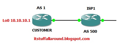
For some practical presentation of the MP-BGP protocol I have created a small ISP lab with couple of UPSTREAM providers that will use the IPv6 and IPv4 prefix routing at the same time. This is a common practice nowadays in the ISP enviroment. 

We have a small ISP with two routers the are iBGP speakers and couple of eBGP peers with upstream connections. For those that are familiar with the IPV6 setup and address space this will come easy. I am using /127 networks for the WAN links to simulate only two IP address space in the peer connection. On the same physical link I am using also the IPv4 address to peer with the BGP speaking router. Now let us look at the configs, I will try to clarify every command. For more on MP-BGP protocol , one can read a RFC on that subject - RFC2858.

ISP1
ipv6 unicast-routing    >> important to turn on because by default IPV6 routing is disabled 
!
interface Loopback0
 ip address 1.1.1.1 255.255.255.255
!
interface Loopback1
 no ip address
 ipv6 address 2030:1::1/64   >> I have defined a couple of /64 networks to propagate to AS100
 ipv6 address 2030:2::1/64
 ipv6 address 2030:3::1/64
 ipv6 enable
!
interface FastEthernet0/0   >> dual IP stack  IPv4 and IPv6 address on the WAN link
 ip address 10.0.0.2 255.255.255.252  
 duplex auto
 speed auto
 ipv6 address 2005:1::/127   << /127 networks allows only two IPv6 hosts
 ipv6 enable          << on some routers this is enabled after entering the IP address
!
router bgp 100
 bgp router-id 1.1.1.1
 no bgp default ipv4-unicast  << I have disabled the default behaviour of BGP , as we are using
 bgp log-neighbor-changes          address family concept  >>
 neighbor 10.0.0.1 remote-as 100
 neighbor 2005:1::1 remote-as 100
 ! 
 address-family ipv4          << the address family model for IPV4
  neighbor 10.0.0.1 activate  
  no auto-summary
  no synchronization
 exit-address-family
 !
 address-family ipv6
  neighbor 2005:1::1 activate
  network 2030:1::1/64          << advertising loopback 1 subnets into BGP
  network 2030:2::1/64
  network 2030:3::1/64
 exit-address-family

The Cisco BGP address family identifier (AFI) model was introduced with multiprotocol BGP and is designed to be modular and scalable, and to support multiple AFI and subsequent address family identifier (SAFI) configurations.
As we can see I have defined two address families IPv4 and IPv6 for the BGP peerings. We must use the activate command on every neighbor for the family, or the peer group to make it easier to manage. We must add the peer address and the AS number under the global BGP process, and further activate the neighbor under the family model. 
Now let us look at the rest of the router config, they are pretty much the same.

ISP2
ipv6 unicast-routing
!
interface Loopback0
 ip address 2.2.2.2 255.255.255.255
!
interface Loopback1
 no ip address
 ipv6 address 2010:1::1/64
 ipv6 address 2010:2::1/64
 ipv6 address 2010:3::1/64
 ipv6 enable
!
interface Loopback2
 ip address 22.22.22.1 255.255.255.0 secondary
 ip address 22.22.24.1 255.255.255.0
!
interface FastEthernet0/0
 ip address 10.0.0.1 255.255.255.252
 duplex auto
 speed auto
 ipv6 address 2005:1::1/127
 ipv6 enable
!
interface FastEthernet1/0
 ip address 172.16.1.1 255.255.255.252
 duplex auto
 speed auto
 ipv6 address 2001:1::/127
 ipv6 enable
!
interface FastEthernet2/0
 ip address 173.16.1.1 255.255.255.252
 duplex auto
 speed auto
 ipv6 address 2002:1::/127
 ipv6 enable
!
router bgp 100
 bgp router-id 2.2.2.2
 no bgp default ipv4-unicast
 bgp log-neighbor-changes
 neighbor 10.0.0.2 remote-as 100
 neighbor 2001:1::1 remote-as 200
 neighbor 2002:1::1 remote-as 300
 neighbor 2005:1:: remote-as 100
 neighbor 172.16.1.2 remote-as 200
 neighbor 173.16.1.2 remote-as 300
 !
 address-family ipv4
  neighbor 10.0.0.2 activate
  neighbor 172.16.1.2 activate
  neighbor 173.16.1.2 activate
  no auto-summary
  no synchronization
  network 22.22.22.0 mask 255.255.255.0
  network 22.22.24.0 mask 255.255.255.0
 exit-address-family
 !
 address-family ipv6
  neighbor 2001:1::1 activate
  neighbor 2002:1::1 activate
  neighbor 2005:1:: activate
  neighbor 2005:1:: next-hop-self
  network 2010:1::1/64
  network 2010:2::1/64
  network 2010:3::1/64
 exit-address-family

UPSTREAM1
ipv6 unicast-routing
!
interface Loopback0
 ip address 5.5.5.5 255.255.255.255
!
interface Loopback1
 no ip address
 ipv6 address 2006:1::1/64
 ipv6 address 2006:2::1/64
 ipv6 address 2006:3::1/64
 ipv6 address 2006:4::1/64
!
interface Loopback2
 ip address 55.55.56.1 255.255.255.0 secondary
 ip address 55.55.55.1 255.255.255.0
!
interface FastEthernet0/0
 ip address 172.16.1.2 255.255.255.252
 duplex auto
 speed auto
 ipv6 address 2001:1::1/127
 ipv6 enable
!
router bgp 200
 bgp router-id 5.5.5.5
 no bgp default ipv4-unicast
 bgp log-neighbor-changes
 neighbor 2001:1:: remote-as 100
 neighbor 172.16.1.1 remote-as 100
 !
 address-family ipv4
  neighbor 172.16.1.1 activate
  no auto-summary
  no synchronization
  network 55.55.55.0 mask 255.255.255.0
  network 55.55.56.0 mask 255.255.255.0
 exit-address-family
 !
 address-family ipv6
  neighbor 2001:1:: activate
  network 2006:1::1/64
  network 2006:2::1/64
  network 2006:3::1/64
  network 2006:4::1/64
 exit-address-family

UPSTREAM2
ipv6 unicast-routing
!
interface Loopback0
 ip address 6.6.6.6 255.255.255.255
!
interface Loopback1
 no ip address
 ipv6 address 2020:1::1/64
 ipv6 address 2020:2::1/64
 ipv6 address 2020:3::1/64
 ipv6 address 2020:4::1/64
 ipv6 enable
!
interface Loopback2
 ip address 66.66.67.1 255.255.255.0
!
interface FastEthernet0/0
 ip address 173.16.1.2 255.255.255.252
 duplex auto
 speed auto
 ipv6 address 2002:1::1/127
 ipv6 enable
!
router bgp 300
 bgp router-id 6.6.6.6
 no bgp default ipv4-unicast
 bgp log-neighbor-changes
 neighbor 2002:1:: remote-as 100
 neighbor 173.16.1.1 remote-as 100
 !
 address-family ipv4
  neighbor 173.16.1.1 activate
  no auto-summary
  no synchronization
  network 66.66.66.0 mask 255.255.255.0
  network 66.66.67.0 mask 255.255.255.0
 exit-address-family
 !
 address-family ipv6
  neighbor 2002:1:: activate
  network 2020:1::1/64
  network 2020:2::1/64
  network 2020:3::1/64
  network 2020:4::1/64
 exit-address-family

To see the BGP table we must use some different syntax on the IPV6 address family. First let us look at the BGP table on the ISP2 router, that interconnects every other router in our small topology.

ISP2#sh ip bgp
BGP table version is 6, local router ID is 2.2.2.2
Status codes: s suppressed, d damped, h history, * valid, > best, i - internal,
              r RIB-failure, S Stale
Origin codes: i - IGP, e - EGP, ? - incomplete

   Network          Next Hop            Metric LocPrf Weight Path
*> 22.22.22.0/24    0.0.0.0                  0         32768 i
*> 22.22.24.0/24    0.0.0.0                  0         32768 i
*> 55.55.55.0/24    172.16.1.2               0             0 200 i
*> 55.55.56.0/24    172.16.1.2               0             0 200 i
*> 66.66.67.0/24    173.16.1.2               0             0 300 i

The BGP table looks simple and clean. We have routes from internal and external neighbors in our table correctly installed. We can test the IPV4 data plane with a simple ping. And verify that it is working fine.

ISP2#ping 66.66.67.1
Type escape sequence to abort.
Sending 5, 100-byte ICMP Echos to 66.66.67.1, timeout is 2 seconds:
!!!!!
Success rate is 100 percent (5/5), round-trip min/avg/max = 20/24/40 ms

Now, let us look a the IPV6 BGP table and the IPV6 family neighbors. Cisco introduces a new command to verify the IPV6 neighbor connectivity and the BGP table.


ISP2#sh ip bgp ipv6 unicast summary
BGP router identifier 2.2.2.2, local AS number 100
BGP table version is 15, main routing table version 15
14 network entries using 2086 bytes of memory
14 path entries using 1064 bytes of memory
5/4 BGP path/bestpath attribute entries using 620 bytes of memory
2 BGP AS-PATH entries using 48 bytes of memory
0 BGP route-map cache entries using 0 bytes of memory
0 BGP filter-list cache entries using 0 bytes of memory
BGP using 3818 total bytes of memory
BGP activity 23/4 prefixes, 23/4 paths, scan interval 60 secs

Neighbor        V    AS MsgRcvd MsgSent   TblVer  InQ OutQ Up/Down  State/PfxRcd
2001:1::1       4   200      64      67       15    0    0 00:59:34        4
2002:1::1       4   300      47      51       15    0    0 00:42:28        4
2005:1::        4   100     297     297       15    0    0 04:51:16       3

We can see that we have three IPV6 BGP neighbors, two external and one internal BGP speaking router. The prefixes are exhanged between them. Now , let us see the IPV6 BGP routing table.

ISP2#sh ip bgp ipv6 unicast
BGP table version is 15, local router ID is 2.2.2.2
Status codes: s suppressed, d damped, h history, * valid, > best, i - internal,
              r RIB-failure, S Stale
Origin codes: i - IGP, e - EGP, ? - incomplete

   Network          Next Hop            Metric LocPrf Weight Path
*> 2006:1::/64      2001:1::1                0             0 200 i
*> 2006:2::/64      2001:1::1                0             0 200 i
*> 2006:3::/64      2001:1::1                0             0 200 i
*> 2006:4::/64      2001:1::1                0             0 200 i
*> 2010:1::1/64     ::                       0         32768 i
*> 2010:2::1/64     ::                       0         32768 i
*> 2010:3::1/64     ::                       0         32768 i
*> 2020:1::/64      2002:1::1                0             0 300 i
*> 2020:2::/64      2002:1::1                0             0 300 i
*> 2020:3::/64      2002:1::1                0             0 300 i
*> 2020:4::/64      2002:1::1                0             0 300 i
*>i2030:1::/64      2005:1::                 0    100      0 i
*>i2030:2::/64      2005:1::                 0    100      0 i
*>i2030:3::/64      2005:1::                 0    100      0 i

We can see all the prefixes from the advertised IPV6 loopbacks that are insalled in the global IPV6 routing table. We can do a simple ping to verify connectivity. I can verify that it is working ok.

ISP2#ping ipv6 2020:1::1 source loopback 1
Type escape sequence to abort.
Sending 5, 100-byte ICMP Echos to 2020:1::1, timeout is 2 seconds:
Packet sent with a source address of 2010:1::1
!!!!!
Success rate is 100 percent (5/5), round-trip min/avg/max = 16/20/28 ms

There is much more to talk about the MP-BGP protocol, and more blogs to come on L3 MPLS VPN, where we will exchange the VPNV4 and VPNV6 routes. On detailed implementation one can always use the Cisco site on MP-BGP for IPV6.

Feel free to comment.

Thursday, August 29, 2013

Virtual Routing and Forwarding

Use VRF-Lite in a SDN model networks

Nowadays we are surrounded in a simplified networking models that have abstracted approach to network management and operations. This abstracted approach is called Software Defined Networking and can simplify every network design. 
Every routing node would be useless if it did not operate in separate processes for every task we configure it to su. Virtual routing and forwarding allows multiple instances of routing table to exist on the same physical device at the same time. This allows us to create VPNs that use the same address space. It also allows us to logically separate subnets inside these virtual tables. We can try do describe the VRFs as similar to the VLAN technology under the Layer 2. Every prefix is isolated in a separate VRF. In this blog I will demonstrate the VRF-Lite feature , that most certain every router can use. Te following topology uses a two customer relationship with an ISP. Each of those customers has two sites.

Subnets on each of the customer sites are in a separate prefix , but the each of the customers is using the same RFC1918 ip address space. First we need to define the links between the customers and define the VRF tables. 
Virtual routing and forwarding can be easily created on the SP router with the IP VRF <name> command.
We will use the OSPF protocol to forward routes between the sites and the Service provider network. Now let us look at the configs of the SP routers.

SERVICE_PROVIDER
ip vrf CE_1
!
ip vrf CE_2
!
interface Loopback0
 ip address 100.100.100.1 255.255.255.255
!
interface Ethernet0/0
 description LINK_TO_CE1_1
 ip vrf forwarding CE_1             >> to turn on VRF table forwarding on the router use ip vrf
 ip address 10.0.0.1 255.255.255.252
 half-duplex
!
interface Ethernet0/1
 description LINK_TO_CE2_2
 ip vrf forwarding CE_2
 ip address 10.0.0.1 255.255.255.252
 half-duplex
!
interface Ethernet0/2
 description LINK_TO_CE1_1
 ip vrf forwarding CE_1
 ip address 10.0.1.1 255.255.255.252
 half-duplex
!
interface Ethernet0/3
 description LINK_TO_CE2_1
 ip vrf forwarding CE_2
 ip address 10.0.1.1 255.255.255.252
 half-duplex
!
router ospf 1 vrf CE_1
 log-adjacency-changes
 network 10.0.0.0 0.0.0.3 area 0
 network 10.0.1.0 0.0.0.3 area 0
!
router ospf 2 vrf CE_2
 log-adjacency-changes
 network 10.0.0.0 0.0.0.3 area 0
 network 10.0.1.0 0.0.0.3 area 0

Every link to the CE_1 and CE_2 has a command IP vrf forwarding included. This tells the SP router to settle in every advertised prefix routing protocol information from that link to a particular VRF table.
We have created two VRF tables: VRF CE_1 and CE_2. With that in mind we associate every interface to its corresponding VRF table. VRF table keeps a logically separated routing prefix information, that is not known to the global table. We can see that the global table knows only the connected routs. As for the OSPF , every process can be associated with a particular VRF so OSPF calculations are kept in a VRF tables, not interleaving with other tables. This is also a good security feature.

SERVICE_PROVIDER#show ip route
Codes: C - connected, S - static, R - RIP, M - mobile, B - BGP
       D - EIGRP, EX - EIGRP external, O - OSPF, IA - OSPF inter area
       N1 - OSPF NSSA external type 1, N2 - OSPF NSSA external type 2
       E1 - OSPF external type 1, E2 - OSPF external type 2
       i - IS-IS, su - IS-IS summary, L1 - IS-IS level-1, L2 - IS-IS level-2
       ia - IS-IS inter area, * - candidate default, U - per-user static route
       o - ODR, P - periodic downloaded static route

Gateway of last resort is not set

     100.0.0.0/32 is subnetted, 1 subnets
C       100.100.100.1 is directly connected, Loopback0

Now let us finish the other configs on the clients routing. I will redistribute the loopacks of the CE routers with subnets shown in the graphic topology. Every CE router will also have a OSPF protocol designed to exchange routes between the CE sites.

CE1_1
interface Loopback0
 ip address 172.16.1.1 255.255.255.0
!
interface Ethernet0/0
 ip address 10.0.0.2 255.255.255.252
 half-duplex
!
router ospf 1
 log-adjacency-changes
 redistribute connected metric 10 subnets
 network 10.0.0.0 0.0.0.3 area 0

CE2_2
interface Loopback0
 ip address 172.16.1.1 255.255.255.0
!
interface Ethernet0/0
 ip address 10.0.0.2 255.255.255.252
 half-duplex
!
router ospf 1
 log-adjacency-changes
 redistribute connected metric 10 subnets
 network 10.0.0.0 0.0.0.3 area 0

CE2_1
interface Loopback0
 ip address 192.168.1.1 255.255.255.0
!
interface Ethernet0/0
 ip address 10.0.1.2 255.255.255.252
 half-duplex
!
router ospf 1
 log-adjacency-changes
 redistribute connected metric 10 subnets
 network 10.0.1.0 0.0.0.3 area 0

CE1_2
interface Loopback0
 ip address 192.168.1.1 255.255.255.0
!
interface Ethernet0/0
 ip address 10.0.1.2 255.255.255.252
 half-duplex
!
router ospf 1
 log-adjacency-changes
 redistribute connected metric 10 subnets
 network 10.0.1.0 0.0.0.3 area 0

The client routers have now stored the OSPF routes from their sites in the routing table. So every customer has connected their sites and exchanged the routes. We can test this.

CE1_2#sh ip route
Codes: C - connected, S - static, R - RIP, M - mobile, B - BGP
       D - EIGRP, EX - EIGRP external, O - OSPF, IA - OSPF inter area
       N1 - OSPF NSSA external type 1, N2 - OSPF NSSA external type 2
       E1 - OSPF external type 1, E2 - OSPF external type 2
       i - IS-IS, su - IS-IS summary, L1 - IS-IS level-1, L2 - IS-IS level-2
       ia - IS-IS inter area, * - candidate default, U - per-user static route
       o - ODR, P - periodic downloaded static route

Gateway of last resort is not set

     172.16.0.0/24 is subnetted, 1 subnets
O E2    172.16.1.0 [110/10] via 10.0.1.1, 00:14:19, Ethernet0/0
     10.0.0.0/30 is subnetted, 2 subnets
O       10.0.0.0 [110/20] via 10.0.1.1, 00:14:19, Ethernet0/0
C       10.0.1.0 is directly connected, Ethernet0/0
C    192.168.1.0/24 is directly connected, Loopback0

CE1_1#sh ip route
Codes: C - connected, S - static, R - RIP, M - mobile, B - BGP
       D - EIGRP, EX - EIGRP external, O - OSPF, IA - OSPF inter area
       N1 - OSPF NSSA external type 1, N2 - OSPF NSSA external type 2
       E1 - OSPF external type 1, E2 - OSPF external type 2
       i - IS-IS, su - IS-IS summary, L1 - IS-IS level-1, L2 - IS-IS level-2
       ia - IS-IS inter area, * - candidate default, U - per-user static route
       o - ODR, P - periodic downloaded static route

Gateway of last resort is not set

     172.16.0.0/24 is subnetted, 1 subnets
C       172.16.1.0 is directly connected, Loopback0
     10.0.0.0/30 is subnetted, 2 subnets
C       10.0.0.0 is directly connected, Ethernet0/0
O       10.0.1.0 [110/20] via 10.0.0.1, 00:14:51, Ethernet0/0
O E2 192.168.1.0/24 [110/10] via 10.0.0.1, 00:14:51, Ethernet0/0

Let us now ping a CE_1 site to site loopback LAN address.

CE1_1#ping 192.168.1.1

Type escape sequence to abort.
Sending 5, 100-byte ICMP Echos to 192.168.1.1, timeout is 2 seconds:
!!!!!
Success rate is 100 percent (5/5), round-trip min/avg/max = 12/32/48 ms

We have a working data plane over the Service provider infrastructure. Our routes with same private address space are stored in seprate VRFs and they can communicate via the same physical router. 
We can still verify the VRF routing table on the SP routers.

SERVICE_PROVIDER#sh ip route vrf CE_1
Routing Table: CE_1
Codes: C - connected, S - static, R - RIP, M - mobile, B - BGP
       D - EIGRP, EX - EIGRP external, O - OSPF, IA - OSPF inter area
       N1 - OSPF NSSA external type 1, N2 - OSPF NSSA external type 2
       E1 - OSPF external type 1, E2 - OSPF external type 2
       i - IS-IS, su - IS-IS summary, L1 - IS-IS level-1, L2 - IS-IS level-2
       ia - IS-IS inter area, * - candidate default, U - per-user static route
       o - ODR, P - periodic downloaded static route

Gateway of last resort is not set

     172.16.0.0/24 is subnetted, 1 subnets
O E2    172.16.1.0 [110/10] via 10.0.0.2, 00:17:10, Ethernet0/0
     10.0.0.0/30 is subnetted, 2 subnets
C       10.0.0.0 is directly connected, Ethernet0/0
C       10.0.1.0 is directly connected, Ethernet0/2
O E2 192.168.1.0/24 [110/10] via 10.0.1.2, 00:17:10, Ethernet0/2

This is routing Layer virtualization of routing information. It is a cool feature and heavily used under the production hood. There is much to write on this subject in complex scenarios. So more to come.

Feel free to comment.

HSRP protocol - host redundancy

Configure HSRP redundancy


HSRP is Cisco's standard method of providing high network availability by providing first-hop redundancy for IP hosts on an IEEE 802 LAN configured with a default gateway IP address.

In this blog we have a host that has no clue what is happening behind a switch it is connected to. Main goal we want to achieve in this scenario is to create a redundant links for the traffic that is not on the PC-s subnet. We will achieve a redundant plan if one router fails, other is routing for the remote subnets.

First we should configure the IP addresses of the XP1 client and the router interfaces connected to each end point. We will chose the 10.0.0.254 address as the active failover IP address. This address will be the virtual ip address as the default gateway for the XP client.


The config scripts look like this:

R1
interface FastEthernet0/0
 ip address 10.0.0.1 255.255.255.0
 duplex auto
 speed auto
 standby 1 ip 10.0.0.254  << virtual IP
 standby 1 timers 5 15   << hold down timers
 standby 1 priority 200  << HSRP priority (100 is default priority router)
 standby 1 preempt   << allows a router with a higher priority to become a master router
 standby 1 track FastEthernet1/0 110  << tracks changes on interfaces not configured with HSRP, if they fail

interface FastEthernet1/0
 ip address 192.168.1.1 255.255.255.0
 duplex auto
 speed auto
!
router ospf 1
 log-adjacency-changes
 passive-interface FastEthernet0/0
 network 0.0.0.0 255.255.255.255 area 0


R2
interface FastEthernet0/0
 ip address 10.0.0.2 255.255.255.0
 duplex auto
 speed auto
 standby 1 ip 10.0.0.254
 standby 1 timers 5 15
 standby 1 preempt
 standby 1 track FastEthernet1/0
!
interface FastEthernet1/0
 ip address 192.168.1.2 255.255.255.0
 duplex auto
 speed auto
!
router ospf 1
 log-adjacency-changes
 passive-interface FastEthernet0/0
 network 0.0.0.0 255.255.255.255 area 0

To verify that HSRP is running we use a simple show output. R1 is the active and R2 is the standby router. They have now agreed on the HSRP parameters and serving the Virtual IP 10.0.0.254 address.

R1#sh standby
FastEthernet0/0 - Group 1
  State is Active
    2 state changes, last state change 00:14:11
  Virtual IP address is 10.0.0.254
  Active virtual MAC address is 0000.0c07.ac01
    Local virtual MAC address is 0000.0c07.ac01 (v1 default)
  Hello time 5 sec, hold time 15 sec
    Next hello sent in 3.660 secs
  Preemption enabled
  Active router is local
  Standby router is 10.0.0.2, priority 100 (expires in 13.904 sec)
  Priority 200 (configured 200)
    Track interface FastEthernet1/0 state Up decrement 110
  IP redundancy name is "hsrp-Fa0/0-1" (default)

R2#sh standby
FastEthernet0/0 - Group 1
  State is Standby
    1 state change, last state change 00:04:06
  Virtual IP address is 10.0.0.254
  Active virtual MAC address is 0000.0c07.ac01
    Local virtual MAC address is 0000.0c07.ac01 (v1 default)
  Hello time 5 sec, hold time 15 sec
    Next hello sent in 3.196 secs
  Preemption enabled
  Active router is 10.0.0.1, priority 200 (expires in 12.932 sec)
  Standby router is local
  Priority 100 (default 100)
    Track interface FastEthernet1/0 state Up decrement 10
  IP redundancy name is "hsrp-Fa0/0-1" (default)

To join the same Backbone area I will configure the R3 router with the same area ID and exhange a loopback address of 172.16.1.1 for testing purposes.

R3
interface Loopback1
 ip address 172.16.1.1 255.255.255.0
!
interface FastEthernet0/0
 ip address 192.168.1.3 255.255.255.0
 duplex auto
 speed auto
!
router ospf 1
 log-adjacency-changes
 network 0.0.0.0 255.255.255.255 area 0

We can see in the Routing table of R3 router, that it received the 10.0.0.0/24 prefix with equal OSPF calculations, so the router will load balance the networks.
Gateway of last resort is not set

R3#show ip route
     172.16.0.0/24 is subnetted, 1 subnets
C       172.16.1.0 is directly connected, Loopback1
     10.0.0.0/24 is subnetted, 1 subnets
O       10.0.0.0 [110/2] via 192.168.1.2, 00:06:48, FastEthernet0/0
                        [110/2] via 192.168.1.1, 00:06:48, FastEthernet0/0
C    192.168.1.0/24 is directly connected, FastEthernet0/0

To make an initial test of the HSRP setup, I will let a continuous ping from the XP1 machine and shutdown one of the R1 interfaces, because this is the active router.


We have seen that if the transition from one state to another in the HSRP setup gained us succesfull redundancy with only 16% of lost traffic. This is minimal, and can be tuned to even less. Take a look at the log messages of the R1.

*Mar  1 00:43:14.339: %HSRP-5-STATECHANGE: FastEthernet0/0 Grp 1 state Active -> Init

Simple enough R2 became an Active router for the 10.0.0.254 virtual IP address. If the second interfaces did fail. The interfaces that is exchanging the OSPF data with the R3, convergence time will not only rely on the timers for the HSRP protocol. Convergence time will wait untill the OSPF proccess does the calculation, and updates the database with the neighbor down message.

This is all for now. Very cool technology.

Feel free to comment.

Reduce BGP router utilization using ORF

Implementing outbound route filtering in BGP


The BGP Prefix Based Outbound Route Filtering feature uses Border Gateway Protocol (BGP) outbound route filter (ORF) send and receive capabilities to minimize the number of BGP updates that are sent between BGP peers. Configuring this feature can help reduce the amount of system resources required for generating and processing routing updates by filtering out unwanted routing updates at the source.

This cool feature could be very useful when a Customer router is filtering and receiving the FULL Internet routing table that could be heavy as 200 MB, with over 300,000 prefixes. This way the router will not have so many processing of the filtered routes and free up a lot of system resources. In our example we have a couple of routers in a simple isp-customer PE-CE network topology.


I will configure a simple BGP peering topology between the PE and the CE router. The CE router will receive the default route from the ISP router. The Customer router does not need the full BGP routing table, maybe it is a stub router, or the default route is enough for all the Internet information the customer wants. So in order to fulfill that scenario a prefix list should be created to filter out the unnecessary routes. Before I applied a prefix list let us look at the BGP table of the CE router. The routes installed are simulated from the loopbacks address. This could also be a full Internet routing table in a production enviroment.


Now let us finish the peering and create a filter to chose only a couple of networks and a default route.

CE
router bgp 65535
 no synchronization
 bgp router-id 2.2.2.2
 bgp log-neighbor-changes
 neighbor 192.168.1.2 remote-as 999
 neighbor 192.168.1.2 prefix-list ISP_IN in
 no auto-summary

ip prefix-list ISP_IN seq 10 permit 0.0.0.0/0
ip prefix-list ISP_IN seq 20 permit 10.10.10.0/24
ip prefix-list ISP_IN seq 30 permit 20.20.20.0/24

PE
router bgp 999
 no synchronization
 bgp router-id 1.1.1.1
 bgp log-neighbor-changes
 redistribute connected
 neighbor 192.168.1.1 remote-as 65535
 neighbor 192.168.1.1 default-originate
 no auto-summary
!
ip route 0.0.0.0 0.0.0.0 Null0

The filters are now working fine on the CE router. The BGP RIB is now much smaller and the CE router has only the desired routes we have assigned to him.

CE#sh ip bgp
BGP table version is 25, local router ID is 2.2.2.2
Status codes: s suppressed, d damped, h history, * valid, > best, i - internal,
              r RIB-failure, S Stale
Origin codes: i - IGP, e - EGP, ? - incomplete

   Network          Next Hop            Metric LocPrf Weight Path
*> 0.0.0.0          192.168.1.2                   0             0 999 i
*> 10.10.10.0/24    192.168.1.2              0             0 999 ?
*> 20.20.20.0/24    192.168.1.2              0             0 999 ?

But what happens under the hood can be seen on the DEBUG BGP updates output. The router is denying all other routes from the PE router. In our case this is not a big problem because of the smaller RIB table, but if we could have the FULL Internet routing table this list could be very long and CPU intensive.


The CE router is generating a DENIED message for every prefix the is not destined for the routing table. This messages generating has very CPU intensive task issuing for the router, and this is why we should try he outbound route filtering.

Outbound route filtering is a dynamic mechanism. It mean it should be configured on both the routers. As we have seen , the CE router is filtering the routes he is receiving from the PE routes. When we have ORF in place the CE router can send dynamic ORF messages to the BGP PE speaking router, that will inform the PE router which updates should be sent over the peer connection. This means that the CE router is telling the PE router how to perform an outbound filtering for his routing table.

To implement it we can use two simple commands under the BGP process of the PE and CE routers.

CE(config-router)#neighbor 192.168.1.2 capability orf prefix-list send
PE(config-router)#neighbor 192.168.1.1 capability orf prefix-list receive

To verify the BPG neighbor capabilities of the CE router:

 AF-dependant capabilities:
    Outbound Route Filter (ORF) type (128) Prefix-list:
      Send-mode: advertised
      Receive-mode: received
  Outbound Route Filter (ORF): sent;
  Incoming update prefix filter list is ISP_IN
                                 Sent       Rcvd
  Prefix activity:               ----       ----
    Prefixes Current:               0          3 (Consumes 156 bytes)
    Prefixes Total:                 0          4
    Implicit Withdraw:              0          1
    Explicit Withdraw:              0          0
    Used as bestpath:             n/a          3
    Used as multipath:            n/a          0

We did not create a prefix filter on the PE router for the 3 routes the CE is interested, but if we do a show output of received information from the CE router we can verify that the we have the current prefix list.

PE#sh ip bgp neighbors 192.168.1.1 received prefix-filter
Address family: IPv4 Unicast
ip prefix-list 192.168.1.1: 3 entries
   seq 10 permit 0.0.0.0/0
   seq 20 permit 10.10.10.0/24
   seq 30 permit 20.20.20.0/24

The final verification is to see once more debug on the CE router. We should verify if the ORF is downsizing the DENIED messages on the CE router for the denied prefixes.


First look at this debug, we can see that now the CE router is only receiving the PREFIXES that it requested. No extra overhead BGP update traffic is getting into the RIB of the CE router. This is greatly reducing the convergence time and offloading the CPU usage.
If wee need to add more routes to the BGP routing table of the CE router, we can use a route refresh with the inbound prefix filter.

CE#clear ip bgp 999 in prefix-filter

On further more granular use of the ORF one can look into the Cisco guid on the web.

Feel free to comment.

Tuesday, August 27, 2013

Configure BGP TTL Security

BGP TTL Security feature


Default behaviour of BGP clients is to send an BGP update messages to peer with a TTL value of 1. There are a ways to remedy this configuration with neighbor statements but we are interested in security in this blog.
This small scenario of couple of eBGP peers will let us demonstrate this security feature.
If we send an BGP update with a TTL value of 1 , this mean that the router needs to be connected directly to the peer it is homing with. It is very easy for an attacker that is simulating a SYN packet on the TCP port 179 where a BGP speaker is listening, to change the TTL value of the SYN requests. Many of these packets could bring down the peering and migitiate a serious DOS attack. This could cause harm on a production enviroment. 

We could prevent this , by configuring (we must do this on both sides) a TTL security hop count for the eBGP neighbors. This way it is very hard for an attacker to simulate a correct TTL value we have assigned to the neighbor statements.

Let us try the configuration scripts:

ISP1(config-router)#neighbor 192.168.1.2 ttl-security hops 1

And if we do and clear ip bgp * we can see in the output that we have no peering yet.

ISP1#sh ip bgp summary
BGP router identifier 1.1.1.1, local AS number 500
BGP table version is 2, main routing table version 2
2 network entries using 234 bytes of memory
2 path entries using 104 bytes of memory
6/1 BGP path/bestpath attribute entries using 744 bytes of memory
2 BGP AS-PATH entries using 48 bytes of memory
0 BGP route-map cache entries using 0 bytes of memory
0 BGP filter-list cache entries using 0 bytes of memory
BGP using 1130 total bytes of memory
BGP activity 17/15 prefixes, 20/18 paths, scan interval 60 secs

Neighbor        V    AS MsgRcvd MsgSent   TblVer  InQ OutQ Up/Down  State/PfxRcd
172.16.1.2      4   500     256     265        2    0    0 00:00:36        2
192.168.1.2     4     1     479     495        0    0    0 00:00:37 OpenSent

Now let us do it on the other side for the customer router. We can see that the hold down period has expired. 
*Mar  1 04:08:10.142: %BGP-3-NOTIFICATION: sent to neighbor 192.168.1.1 4/0 (hold time expired) 0 bytes


So we must put in the exact same TTL hops in the customer neighbor statement.

CUSTOMER(config-router)#neighbor 192.168.1.1 ttl-security hops 1


And after a couple of seconds we have our peering up and running.

*Mar  1 04:10:39.186: %BGP-5-ADJCHANGE: neighbor 192.168.1.1 Up


So let us look a the final configs at the BGP processes. 

CUSTOMER#sh running-config | section bgp
router bgp 1
 no synchronization
 bgp router-id 10.10.10.10
 bgp log-neighbor-changes
 bgp scan-time 20
 network 50.50.50.0 mask 255.255.255.0
 network 100.100.100.0 mask 255.255.255.0
 redistribute connected
 neighbor 192.168.1.1 remote-as 500
 neighbor 192.168.1.1 ttl-security hops 1
 neighbor 192.168.1.1 timers 20 60
 neighbor 192.168.1.1 advertisement-interval 15
 no auto-summary


ISP1#sh running-config | section bgp
router bgp 500
 no synchronization
 bgp router-id 1.1.1.1
 bgp log-neighbor-changes
 network 1.1.1.1 mask 255.255.255.255
 neighbor 172.16.1.2 remote-as 500
 neighbor 172.16.1.2 next-hop-self
 neighbor 192.168.1.2 remote-as 1
 neighbor 192.168.1.2 ttl-security hops 1
 neighbor 192.168.1.2 soft-reconfiguration inbound
 no auto-summary

This feature is explained more on the RFC5082

Feel free to comment.

BGP Soft Reconfiguration Inbound

Configure soft reconfiguration inbound


When a BGP speaking router advertises routes another BGP router updates his BGP table with the same. But there are some situations where an network engineer want's to apply an inbound policy for the routes that the organization is receiving. Because of the BGP protocol design , the BGP Update messages sent to peers are incremental, and if one want's to filter the complete tables and prefixes it must use a hard reset or a route refresh (sometimes a router does not support this feature). A hard reseting of the bgp peering in a production enviroment is not a good thing. 
After this said, I will introduce a mechanism that allows us to store all the untouched NLRI (Network Layer Reachability Information) in a different table that can be filtered later on.  I have attached a small lab diagram to further elaborate the feature.

Let us take a look at the BGP table organization

Adj-RIBs-In --—-> Loc-RIB —---> Adj-RIBs-Out

The Adj-RIBs-In stores UPDATE messages from other BGP speakers. These are un-edited routes received from our neighbor.  Next, our inbound policy is applied, and routes that pass through the policy & have a valid/resolvable next hop, are put into the Loc-RIB. The rest of the routes in the Adj-RIBs-In are discarded.

The Adj-RIBs-Out stores routing information that the BGP speaker will advertise to its peers (i.e. routes that have passed through outbound policies & will be sent in the BGP UPDATE messages to other peers). This is actually just a pointer back to the record in the Loc-RIB.

Soft reconfiguration allows you to store a copy of the Adj-RIB-in.  

We can configure the soft reconfiguration on the ISP router so one can filter the routes from the Customer.
First to clarify that the soft inbound is not reconfigured and we cannot see the unfiltered routes.

ISP1#sh ip bgp neighbors 192.168.1.2 received-routes
% Inbound soft reconfiguration not enabled on 192.168.1.2

We use a simple command to configure it.

ISP1(config-router)#neighbor 192.168.1.2 soft-reconfiguration inbound


Now if we try the show output for the received routes on the ISP we can see all the routes with their original NLRI data sent over the BGP peering.


ISP1#sh ip bgp neighbors 192.168.1.2 received-routes
BGP table version is 28, local router ID is 1.1.1.1
Status codes: s suppressed, d damped, h history, * valid, > best, i - internal, r RIB-failure, S Stale
Origin codes: i - IGP, e - EGP, ? - incomplete

   Network          Next Hop            Metric LocPrf Weight Path
*> 10.10.10.10/32   192.168.1.2             0             0 1 ?
*> 15.15.15.0/24    192.168.1.2              0             0 1 ?
*> 15.15.16.0/24    192.168.1.2              0             0 1 ?
*> 15.15.17.0/24    192.168.1.2              0             0 1 ?
*> 50.50.50.0/24    192.168.1.2              0             0 1 i
*> 100.100.100.0/24 192.168.1.2           0             0 1 i
r> 192.168.1.0/30   192.168.1.2             0             0 1 ?

Total number of prefixes 7

We can see the last NLRI that has a r> sign in front of the data. That tells us that there is a RIB failure for that particular route. If we do a show command for that route we can see that there is route in the routing table with a smaller AD. This is the attached interface on the ISP1 router.

ISP1#sh ip route 192.168.1.0
Routing entry for 192.168.1.0/30, 1 known subnets
  Attached (1 connections)
C       192.168.1.0 is directly connected, FastEthernet2/0

Soft reconfiguration inbound utilizies a lot of memory resources on the router. So it is better not to use this feature on every router, in every scenario.

Feel free to comment.

Tune BGP Timers

How to configure BGP timers

BGP timers are used in peering procedure with iBGP and eBGP speaking routers. In this blog I will try to explain where to use and how to tune and benefit for BGP timers. First let us see the basic timers:
  • KEEPALIVE and HOLD-DOWN
  • ADVERTISEMENT INVERVAL
  • SCAN-TIMER 
Keepalive and hold-down timers are the most common in BGP peerings. Using the default settings, the keepalive timer is 60 seconds and hold-down timer is 3 x keepalive or 180 seconds.When we have a successfull peering, router counts from 0 to every second up. Every keepalive packet a router receives from the neighbor resets the BGP timer and the count procedure starts again. If a router does not send keep alives packets three in a row the default BGP hold-down timer expires. This will reproduce a hold down period expired and the peering will go down. Thus the routes from the iBGP speaking router will not be advertised from the neighbor router. We do not want that to happen often in the production enviroment. 

Let us see a small lab diagram and test the timer tuning configs.

We can use the show command to see the output of the default BGP timer values on one of the eBGP peers. We can look at the customer router.

CUSTOMER#sh ip bgp neighbors 192.168.1.1
BGP neighbor is 192.168.1.1,  remote AS 500, external link
  BGP version 4, remote router ID 1.1.1.1
  BGP state = Established, up for 01:35:20
  Last read 00:00:20, last write 00:00:20, hold time is 180, keepalive interval is 60 seconds
  Default minimum time between advertisement runs is 30 seconds

In order to keep the BGP table stable BGP speaking router maintains a period of advertising the routes to the neighboring router. This period is called advertisiment timer. The default timer for the iBGP router is 0 seconds and for the eBGP routes is 30 seconds.
Service providers often agree on what should be the BGP timers set on their sides, depending on what services is the router carrying. In our situation we will change to smaller values to improve convergence in case of failures. 

We will set the the keepalive to 20 seconds and the hold down timer to 60 seconds. To send this settings to eBGP peers, we should reset the BGP peering with the clear ip bgp * (note the the soft reconfiguration will not work under these cases).

CUSTOMER(config-router)#neighbor 192.168.1.1 timers 20 60

CUSTOMER#sh running-config | section bgp
router bgp 1
 no synchronization
 bgp router-id 10.10.10.10
 bgp log-neighbor-changes
 network 50.50.50.0 mask 255.255.255.0
 network 100.100.100.0 mask 255.255.255.0
 neighbor 192.168.1.1 remote-as 500
 neighbor 192.168.1.1 timers 20 60
 no auto-summary

CUSTOMER#clear ip bgp *
*Mar  1 02:08:14.423: %BGP-5-ADJCHANGE: neighbor 192.168.1.1 Up

We can verify now that the settings took place and we have a smaller time frame set on the current BGP peering with the eBGP router.

CUSTOMER#sh ip bgp neighbors 192.168.1.1
BGP neighbor is 192.168.1.1,  remote AS 500, external link
  BGP version 4, remote router ID 1.1.1.1
  BGP state = Established, up for 00:00:33
  Last read 00:00:13, last write 00:00:01, hold time is 60, keepalive interval is 20 seconds

Now we should tweak the advertisiment timer under the BGP proccess. We will set the routes refresh for 10 seconds. This is more than enough for this type of connection.

CUSTOMER(config-router)#neighbor 192.168.1.1 advertisement-interval 15

We can se from the output of the BGP neighbor on the Customer router we have some advertisement activity. And the default timer is now configured to 15 seconds as we told the router to do.

 For address family: IPv4 Unicast
  BGP table version 5, neighbor version 5/0
 Output queue size : 0
  Index 1, Offset 0, Mask 0x2
  1 update-group member
                                 Sent       Rcvd
  Prefix activity:               ----       ----
    Prefixes Current:               2          2 (Consumes 104 bytes)
    Prefixes Total:                 2          2
    Implicit Withdraw:              0          0
    Explicit Withdraw:              0          0
    Used as bestpath:             n/a          2
    Used as multipath:            n/a          0

                                   Outbound    Inbound
  Local Policy Denied Prefixes:    --------    -------
    Bestpath from this peer:              2        n/a
    Total:                                2          0
  Number of NLRIs in the update sent: max 2, min 2
  Minimum time between advertisement runs is 15 seconds


One more last timer we should include in this blog is the BGP-SCANNER. BGP scan time defines the period that the router will retry to scan the complete routing table. As the table grow larger, a complete Internet routing table could get up to 200 MB, default time is 60 seconds. The Scan process of BGP protocol looks inside the routing table and finds the missing or wrong IGP route for the next-hop , or a better alternative to a prefix using the BGP attributes. We can lower this time if we have enough resources on the router to do this job for us.

CUSTOMER(config-router)#bgp scan-time 20


To verify the actual scanning time we can see it in the summary output.

CUSTOMER#sh ip bgp summary
BGP router identifier 10.10.10.10, local AS number 1
BGP table version is 5, main routing table version 5
4 network entries using 468 bytes of memory
4 path entries using 208 bytes of memory
4/3 BGP path/bestpath attribute entries using 496 bytes of memory
1 BGP AS-PATH entries using 24 bytes of memory
0 BGP route-map cache entries using 0 bytes of memory
0 BGP filter-list cache entries using 0 bytes of memory
BGP using 1196 total bytes of memory
BGP activity 16/12 prefixes, 16/12 paths, scan interval 20 secs

Neighbor        V    AS MsgRcvd MsgSent   TblVer  InQ OutQ Up/Down  State/PfxRcd
192.168.1.1     4   500     178     165        5    0    0 00:11:07        2


So the final configs on our freshly tuned eBGP peer should look like this:

CUSTOMER#show running-config | section bgp
router bgp 1
 no synchronization
 bgp router-id 10.10.10.10
 bgp log-neighbor-changes
 bgp scan-time 20
 network 50.50.50.0 mask 255.255.255.0
 network 100.100.100.0 mask 255.255.255.0
 neighbor 192.168.1.1 remote-as 500
 neighbor 192.168.1.1 timers 20 60
 neighbor 192.168.1.1 advertisement-interval 15
 no auto-summary


Thanks for reading. Feel free to comment.