Showing posts with label OSPF. Show all posts

Friday, October 18, 2013

OSPF LOAD BALANCING

OSPF LOAD BALANCING


Load balancing is a standard functionality of the Cisco IOS® router software, and is available across all router platforms. It is inherent to the forwarding process in the router and is automatically activated if the routing table has multiple paths to a destination. It is based on standard routing protocols, such as Routing Information Protocol (RIP), RIPv2, Enhanced Interior Gateway Routing Protocol (EIGRP), Open Shortest Path First (OSPF), and Interior Gateway Routing Protocol (IGRP), or derived from statically configured routes and packet forwarding mechanisms. It allows a router to use multiple paths to a destination when forwarding packets.

For this short blog I will use the OSPF protocol. In this example a client has two WAN connections with two broadband routers that both use for Internet routing. We will enable and disable a load balancing of packets that are sourcing from the HOST to the WEB SERVER.   Following the diagram:


Now let us look at the configuration scripts of the routers:

R1
hostname R1
!
ip cef
no ip domain lookup
ip domain name lab.local
!
interface Loopback0
 ip address 10.1.1.1 255.255.255.255
 ip ospf network point-to-point
!
interface FastEthernet0/0
 ip address 192.168.1.1 255.255.255.0
 duplex auto
 speed auto
!
router ospf 1
 log-adjacency-changes
 network 0.0.0.0 255.255.255.255 area 0

R2
hostname R2
ip cef
no ip domain lookup
ip domain name lab.local
!
interface Loopback0
 ip address 10.2.1.1 255.255.255.255
 ip ospf network point-to-point
!
interface FastEthernet0/0
 ip address 192.168.1.2 255.255.255.0
 duplex auto
 speed auto
!
interface FastEthernet1/0
 ip address 172.16.1.3 255.255.255.0
 duplex auto
 speed auto
!
router ospf 1
 log-adjacency-changes
 network 0.0.0.0 255.255.255.255 area 0

R3
hostname R3
!
ip cef
no ip domain lookup
ip domain name lab.local
!
interface Loopback0
 ip address 10.3.1.1 255.255.255.255
 ip ospf network point-to-point
!
interface FastEthernet0/0
 ip address 192.168.1.3 255.255.255.0
 duplex auto
 speed auto
!
interface FastEthernet1/0
 ip address 172.16.1.2 255.255.255.0
 duplex auto
 speed auto
!
router ospf 1
 log-adjacency-changes
 network 0.0.0.0 255.255.255.255 area 0

R4
hostname R4
!
ip cef
no ip domain lookup
ip domain name lab.local
!
interface Loopback0
 ip address 10.4.1.1 255.255.255.255
 ip ospf network point-to-point
!
interface Loopback1
 ip address 99.99.99.99 255.255.255.0
!
interface FastEthernet0/0
 ip address 172.16.1.1 255.255.255.0
 duplex auto
 speed auto
!
router ospf 1
 log-adjacency-changes
 network 0.0.0.0 255.255.255.255 area 0

Now we should see how the HOST router sees the route for the WEB SERVER. That is the 99.99.99.99/32 sub Network that we are interested in LOAD BALANCING.

R1#sh ip route

Gateway of last resort is not set

     99.0.0.0/32 is subnetted, 1 subnets
O       99.99.99.99 [110/3] via 192.168.1.3, 00:12:49, FastEthernet0/0    << LOAD 
                             [110/3] via 192.168.1.2, 00:12:49, FastEthernet0/0          BALANCED >>
     172.16.0.0/24 is subnetted, 1 subnets
O       172.16.1.0 [110/2] via 192.168.1.3, 00:12:49, FastEthernet0/0
                   [110/2] via 192.168.1.2, 00:12:49, FastEthernet0/0
     10.0.0.0/32 is subnetted, 4 subnets
O       10.2.1.1 [110/2] via 192.168.1.2, 00:12:49, FastEthernet0/0
O       10.3.1.1 [110/2] via 192.168.1.3, 00:12:50, FastEthernet0/0
C       10.1.1.1 is directly connected, Loopback0
O       10.4.1.1 [110/3] via 192.168.1.3, 00:12:50, FastEthernet0/0
                 [110/3] via 192.168.1.2, 00:12:50, FastEthernet0/0
C    192.168.1.0/24 is directly connected, FastEthernet0/0

After we do a TRACEROUTE to the destination we can see that the packets are passing trough two routers and thus load balancing the traffic:


R1#traceroute 99.99.99.99
Type escape sequence to abort.
Tracing the route to 99.99.99.99
  1 192.168.1.3 52 msec
    192.168.1.2 40 msec
    192.168.1.3 28 msec
  2 172.16.1.1 40 msec *  76 msec

OSPF has a built in Protocol Mechanism that uses parameters to calculate the same link between the host and the EDGE routers. We can disable these two "paths" using the maximum-paths command.

R1#conf t
Enter configuration commands, one per line.  End with CNTL/Z.
R1(config)#router ospf 1
R1(config-router)#maximum-paths 1
R1(config-router)#end

Now let us look at the routing table of Router 1:

R1#sh ip route
Gateway of last resort is not set
     99.0.0.0/32 is subnetted, 1 subnets
O       99.99.99.99 [110/3] via 192.168.1.2, 00:00:37, FastEthernet0/0  <<<ONE PATH>>>
     172.16.0.0/24 is subnetted, 1 subnets
O       172.16.1.0 [110/2] via 192.168.1.2, 00:00:37, FastEthernet0/0
     10.0.0.0/32 is subnetted, 4 subnets
O       10.2.1.1 [110/2] via 192.168.1.2, 00:00:37, FastEthernet0/0
O       10.3.1.1 [110/2] via 192.168.1.3, 00:00:37, FastEthernet0/0
C       10.1.1.1 is directly connected, Loopback0
O       10.4.1.1 [110/3] via 192.168.1.2, 00:00:37, FastEthernet0/0
C    192.168.1.0/24 is directly connected, FastEthernet0/0

And finally we can do a TRACEROUTE to see the packet flow to the destination of the web server:

R1#traceroute 99.99.99.99
Type escape sequence to abort.
Tracing the route to 99.99.99.99

  1 192.168.1.2 28 msec 52 msec 20 msec  <<FIRST HOPE, ONLY ONE ROUTER>>
  2 172.16.1.1 40 msec *  76 msec
R1#

OSPF can be also tuned under the interface level configuration. This can be done using the command syntax: ip load-sharing per packet. Important thing to remember is not to disable CEF on the routers, in that case you can use up all of the CPU resources. This is done , when routers needs to calculate all over again in the routing table for every load balanced network.

Feel free to comment.

Tuesday, September 10, 2013

IPV6 OSPF simple configuration

Simple IPV6 OSPF configuration


Open Shortest Path First (OSPF) is a routing protocol for IP. It is a link-state protocol, as opposed to a distance-vector protocol. A link-state protocol makes routing decisions based on the states of the links that connect source and destination machines. The state of a link is a description of that interface and the relationship to its neighboring networking devices. The interface information includes the IPv6 prefix of the interface, the network mask, the type of network it is connected to, the routers connected to that network, and so forth. This information is propagated in various type of link-state advertisements (LSAs)

Configuring OSPF under IPV6 has small, but simplified implementation techniques. Here are some important differences:
  • Router-ID is still in a 32 bit format (example 1.1.1.1)
  • Area configuration is done on the interface level
  • We can have multiple processes under one interface either logic or physical
Here we have a simple scenario in with two Area OSPF configuration using the IPV6 protocol with sample global prefix IP addresses. 


So , next to examine the config files on all the routers. Router 4 is configured in Area 1 and all of the others are configured under the area 0. Before implementing any command scripts we must type in the following to enable proper IPV6 routing:
  • ipv6 unicast-routing
  • ipv6 cef
This is done on the global connfiguration mode. Let us see the rest of the important configuration on the routers.

R1
interface Loopback0
 ip address 1.1.1.1 255.255.255.255
 ipv6 address 3000::1/128
 ipv6 ospf 1 area 0
!
interface FastEthernet0/0
 no ip address
 duplex auto
 speed auto
 ipv6 address 3500::1/96
 ipv6 ospf 1 area 0
!
interface FastEthernet1/0
 no ip address
 duplex auto
 speed auto
 ipv6 address 2001::1/64
 ipv6 enable
 ipv6 ospf 1 area 1
!
ipv6 router ospf 1
 router-id 1.1.1.1
 log-adjacency-changes

R2
interface Loopback0
 ip address 2.2.2.2 255.255.255.255
 ipv6 address 3000::2/128
 ipv6 enable
 ipv6 ospf 1 area 0
!
interface FastEthernet0/0
 no ip address
 duplex auto
 speed auto
 ipv6 address 3500::2/96
 ipv6 ospf 1 area 0
!
ipv6 router ospf 1
 router-id 2.2.2.2
 log-adjacency-changes

R3
interface Loopback0
 ip address 2.2.2.2 255.255.255.255
 ipv6 address 3000::2/128
 ipv6 enable
 ipv6 ospf 1 area 0
!
interface FastEthernet0/0
 no ip address
 duplex auto
 speed auto
 ipv6 address 3500::2/96
 ipv6 ospf 1 area 0
!
ipv6 router ospf 1
 router-id 2.2.2.2
 log-adjacency-changes

R4
interface Loopback0
 ip address 4.4.4.4 255.255.255.255
 ipv6 address 2002::1/128
 ipv6 enable
 ipv6 ospf 1 area 1
!
interface FastEthernet0/0
 no ip address
 duplex auto
 speed auto
 ipv6 address 2001::2/64
 ipv6 enable
 ipv6 ospf 1 area 1
!
ipv6 router ospf 1
 router-id 4.4.4.4
 log-adjacency-changes

To further examine and verify we see the new changes that are not used under the IPV4 configuration. The area is configured under the interface level  ipv6 ospf 1 area 1. And we have kept the 32 bit format of the router-id address under the global router ospf proccess  router-id 4.4.4.4.

To verify we can see that we have advertised the loopbacks and the wan links. The DR/BDR election is done in similar way like in IPV4. The router-id are our loopback addresses.

R1#sh ipv6 ospf neighbor
Neighbor ID     Pri   State           Dead Time   Interface ID    Interface
2.2.2.2           1   FULL/DROTHER    00:00:39    4               FastEthernet0/0
3.3.3.3           1   FULL/DR         00:00:38    4               FastEthernet0/0
4.4.4.4           1   FULL/DR         00:00:37    4               FastEthernet1/0

Now let us look at the routing table of the R1 as it is playing the role of the ABR router in this scenario.

R1#sh ipv6 route
IPv6 Routing Table - 10 entries
Codes: C - Connected, L - Local, S - Static, R - RIP, B - BGP
       U - Per-user Static route
       I1 - ISIS L1, I2 - ISIS L2, IA - ISIS interarea, IS - ISIS summary
       O - OSPF intra, OI - OSPF inter, OE1 - OSPF ext 1, OE2 - OSPF ext 2
       ON1 - OSPF NSSA ext 1, ON2 - OSPF NSSA ext 2
C   2001::/64 [0/0]
     via ::, FastEthernet1/0
L   2001::1/128 [0/0]
     via ::, FastEthernet1/0
O   2002::1/128 [110/1]    <<< router R1 will propagate this route as InterArea
     via FE80::CE06:FF:FEFC:0, FastEthernet1/0
LC  3000::1/128 [0/0]
     via ::, Loopback0
O   3000::2/128 [110/1]
     via FE80::CE01:FF:FEFC:0, FastEthernet0/0
O   3000::3/128 [110/1]
     via FE80::CE02:FF:FEFC:0, FastEthernet0/0
C   3500::/96 [0/0]
     via ::, FastEthernet0/0
L   3500::1/128 [0/0]
     via ::, FastEthernet0/0
L   FE80::/10 [0/0]
     via ::, Null0
L   FF00::/8 [0/0]
     via ::, Null0

To verify the InterArea connectivity and the routing exchange we will ping the loopback address of the R4 from the R2 router using the loopback as the source address.

R2#ping 2002::1 source loopback 0
Type escape sequence to abort.
Sending 5, 100-byte ICMP Echos to 2002::1, timeout is 2 seconds:
Packet sent with a source address of 3000::2
!!!!!
Success rate is 100 percent (5/5), round-trip min/avg/max = 20/45/72 ms

And we have a success. The routing OSPF domain has fully converged. Simple enough. More to come !!!

Feel free to comment.

OSPF Designated Router Election

OSPF force DR election


A designated router (DR) is the router interface elected among all routers on a particular multiaccess network segment, generally assumed to be broadcast multiaccess. The basic neighbor discovery process (Hello), flooding (224.0.0.6), DR election (priority, RID). Special techniques, often vendor-dependent, may be needed to support the DR function on nonbroadcast multiaccess (NBMA) media. It is usually wise to configure the individual virtual circuits of a NBMA subnet as individual point-to-point lines; the techniques used are implementation-dependent.
Do not confuse the DR with an OSPF router type. A given physical router can have some interfaces that are designated (DR), others that are backup designated (BDR), and others that are non-designated. If no router is DR or BDR on a given subnet, the BDR is first elected, and then a second election is held for the DR.

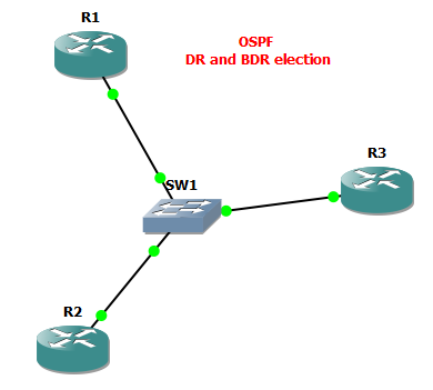
I have created a small Backbone area with three OSPF speaking routers. We can use this small scenario to see the election finished for the DR and the BDR. And also we can force our DR selection process. 


The configs are very simple. Every router has a Loopback IP, that is used as a ROUTER-ID in the OSPF domain. All the routers belong to the AREA 0 and have their connected networks associated to the area.

R1
interface Loopback0
 ip address 1.1.1.1 255.255.255.255
!
interface FastEthernet0/0
 ip address 172.16.1.1 255.255.255.0
 duplex auto
 speed auto
!
router ospf 1
 router-id 1.1.1.1
 log-adjacency-changes
 network 1.1.1.1 0.0.0.0 area 0
 network 172.16.1.0 0.0.0.255 area 0

R2
interface Loopback0
 ip address 2.2.2.2 255.255.255.255
!
interface FastEthernet0/0
 ip address 172.16.1.2 255.255.255.0
 duplex auto
 speed auto
!
router ospf 1
 router-id 2.2.2.2
 log-adjacency-changes
 network 2.2.2.2 0.0.0.0 area 0
 network 172.16.1.0 0.0.0.255 area 0

R3
interface Loopback0
 ip address 3.3.3.3 255.255.255.255
!
interface FastEthernet0/0
 ip address 172.16.1.3 255.255.255.0
 duplex auto
 speed auto
!
router ospf 1
 router-id 3.3.3.3
 log-adjacency-changes
 network 3.3.3.3 0.0.0.0 area 0
 network 172.16.1.0 0.0.0.255 area 0

To verify the DR and the BDR election , we can see the neighbor relationship on the R3. 

R3#sh ip ospf neighbor
Neighbor ID     Pri   State           Dead Time   Address         Interface
1.1.1.1           1   FULL/DR         00:00:36    172.16.1.1      FastEthernet0/0
2.2.2.2           1   FULL/BDR        00:00:32    172.16.1.2      FastEthernet0/0

As we can see , the default election OSPF mechanism used the lowest IP address to elect the DR in the broadcast domain we have created. We can also check the status of the OSPF interface and see the priority for the OSPF election process. 

R1#sh ip ospf interface fastEthernet 0/0
FastEthernet0/0 is up, line protocol is up
  Internet Address 172.16.1.1/24, Area 0
  Process ID 1, Router ID 1.1.1.1, Network Type BROADCAST, Cost: 1
  Transmit Delay is 1 sec, State DR, Priority 1
  Designated Router (ID) 1.1.1.1, Interface address 172.16.1.1
  Backup Designated router (ID) 2.2.2.2, Interface address 172.16.1.2
  Timer intervals configured, Hello 10, Dead 40, Wait 40, Retransmit 5
    oob-resync timeout 40
    Hello due in 00:00:02
  Supports Link-local Signaling (LLS)
  Index 2/2, flood queue length 0
  Next 0x0(0)/0x0(0)
  Last flood scan length is 1, maximum is 1
  Last flood scan time is 0 msec, maximum is 0 msec
  Neighbor Count is 2, Adjacent neighbor count is 2
    Adjacent with neighbor 2.2.2.2  (Backup Designated Router)
    Adjacent with neighbor 3.3.3.3
  Suppress hello for 0 neighbor(s)

We can see a lot from this output. By default the OSPF uses the Highest Priority number for the DR election, and if every router in the BROADCAST network has the same, the the tie breaker is the lowest router-id.

Now we should change the topology. Say the the R3 has higher CPU resoruces and NVRAM capabalities, we will for the OSPF protocol to elect the R3 to become the Designated router for our broadcast network. This is done via a simple command on the interfaces that are responsible for the OSPF Hello packet sending, in our case the F0/0.

R1
R1(config)#interface fastEthernet 0/0
R1(config-if)#ip ospf priority 0
!
R1#clear ip ospf process
Reset ALL OSPF processes? [no]: y

R2
R2(config)#interface fastEthernet 0/0
R2(config-if)#ip ospf priority 0
!
R2#clear ip ospf process
Reset ALL OSPF processes? [no]: y

We have disabled the possibility for the R1 and R2 to become the DR router. After a couple of second we will setup the new , higher priority on the routers, that will force the R3 to become the DR, inspite of the highest router-id.

R1
R1(config)#interface fastEthernet 0/0
R1(config-if)#ip ospf priority 254
!
R1#clear ip ospf process
Reset ALL OSPF processes? [no]: y

R2
R2(config)#interface fastEthernet 0/0
R2(config-if)#ip ospf priority 255
!
R2#clear ip ospf process
Reset ALL OSPF processes? [no]: y

Now to verify the final output. 

R1#sh ip ospf neighbor
Neighbor ID     Pri   State           Dead Time   Address         Interface
2.2.2.2         255   FULL/BDR        00:00:33    172.16.1.2      FastEthernet0/0
3.3.3.3           1   FULL/DR         00:00:37    172.16.1.3      FastEthernet0/0

We can now see that the R3 is the Designated router for the 172.16.1.0/24 subnet and the R2 has been relected as the Backup Designated router.
This is all to it.

Feel free to comment.

Saturday, September 7, 2013

OSPF MD5 Authentification

Configure OSPF MD5 authentification


OSPF protocol relies on  the SPF algorhythm to calculate the changes in the LSA database, propagate LSA packets end form neighbor communication (as many other functions). OSPF is a great IGP in many scenarios, but the packets between the routers and firewalls can be intercepted and spoofed. This can be easily done , to mitigate a DDOS attack on a OSPF speaking router. 
I have configured two OSPF speaking routers to use the MD5 authentification in their backbone area. 


The basic configs to form the AREA 0 connectivity follows:

R1
interface Loopback0
 ip address 1.1.1.1 255.255.255.0
!
interface FastEthernet0/0
 ip address 192.168.1.1 255.255.255.252
 duplex auto
 speed auto
!
router ospf 1
 log-adjacency-changes
 network 0.0.0.0 255.255.255.255 area 0

R2
interface Loopback0
 ip address 2.2.2.2 255.255.255.255
!
interface FastEthernet0/0
 ip address 192.168.1.2 255.255.255.252
 duplex auto
 speed auto
!
router ospf 1
 log-adjacency-changes
 network 0.0.0.0 255.255.255.255 area 0

Now let us configure the MD5 Authentification on the Backbone Area. Notice that every router must use the MD5 encryption. If not that router cannot be apart of the Area 0.

R1
R1(config-router)#area 0 authentication message-digest
R1(config)#interface fastEthernet 0/0
R1(config-if)#ip ospf message-digest-key 1 md5 cisco

R2
R2(config-router)#area 0 authentication message-digest
R2(config)#interface fastEthernet 0/0
R2(config-if)#ip ospf message-digest-key 1 md5 cisco


After entering the auth scripts the neighbors form a relationship once more.
%OSPF-5-ADJCHG: Process 1, Nbr 1.1.1.1 on FastEthernet0/0 from LOADING to FULL, Loading

The last thing that is left is to verify that the OSPF Hello and Update packets are authentificated trough the proper interfaces. This can be done on both routers. 

R1#sh ip ospf interface fastEthernet 0/0
FastEthernet0/0 is up, line protocol is up
  Internet Address 192.168.1.1/30, Area 0
  Process ID 1, Router ID 1.1.1.1, Network Type BROADCAST, Cost: 10
  Transmit Delay is 1 sec, State BDR, Priority 1
  Designated Router (ID) 2.2.2.2, Interface address 192.168.1.2
  Backup Designated router (ID) 1.1.1.1, Interface address 192.168.1.1
  Flush timer for old DR LSA due in 00:01:02
  Timer intervals configured, Hello 10, Dead 40, Wait 40, Retransmit 5
    oob-resync timeout 40
    Hello due in 00:00:05
  Supports Link-local Signaling (LLS)
  Cisco NSF helper support enabled
  IETF NSF helper support enabled
  Index 1/1, flood queue length 0
  Next 0x0(0)/0x0(0)
  Last flood scan length is 1, maximum is 1
  Last flood scan time is 0 msec, maximum is 0 msec
  Neighbor Count is 1, Adjacent neighbor count is 1
    Adjacent with neighbor 2.2.2.2  (Designated Router)
  Suppress hello for 0 neighbor(s)
  Message digest authentication enabled
    Youngest key id is 1

We can see that we have succesfull key exchange now. We can further debug the adjancacies between the routers using the debug ip ospf adj. This is very helpful to see if the OSPF speaking routers will not form the neighbor relationship again.

Fell free to comment.

Saturday, August 31, 2013

Understanding the OSPF protocol

Small introduction to OSPF protocol

OSPF, or Open Shortest Path First, is a link-state, open-standard, dynamic routing protocol.  OSPF uses an algorithm known as SPF, or Dijkstra’s Shortest Path First, to compute internally the best path to any given route.OSPF is classless and converges fairly quickly, using cost as it’s metric.  A router running OSPF creates its own database which contains information on the entire OSPF network, not simply neighbor’s routes like EIGRP.  This allows the router to make intelligent choices about path selection on its own instead of relying exclusively on neighbor information.

OSPF routers do form neighbor relationships though.  They exchange hellos with neighboring routers and in the process learn their neighbor’s Router ID (RID) and cost.  Those values are then sent to the adjacency table. Every router is responsible for computing its own best paths to all destinations within an OSPF domain.  Once the SPF algorithm selects the best paths, they are then eligible to be added to the routing table. 
This protocol is considered as a Interior Gateway Protocol (simple IGP), which is widely used in ISP scenarios as an infrastructure protocol for BGP routing. 

Once a router has exchanged hellos with its neighbors and captured Router IDs and cost information, it begins sending LSAs, or Link State Advertisements.  LSAs contain the RID and costs to the router’s neighbors.  LSAs are shared with every other router in the OSPF domain.  A router stores all of its LSA information (including info it receives from incoming LSAs) in the Link State Database (LSDB).

OSPF is different from EIGRP in that it uses areas to segment routing domains.  This helps partition routers into manageable groups if the layer 3 network begins to get large. It all starts with area 0.  Every OSPF network must contain an area 0, sometimes referred to as the backbone area and every additional area must be physically connected to area 0.  From there, other areas are optional. Note that the SPF algorithm only runs within a single area, so routers only compute paths within their own area.  Inter-area routes are passed using border routers.

OSPF Area types:

Backbone area - Another name for area 0
Regular area - Non-backbone area, with both internal and external routes
Stub area - Contains only internal routes and a default route
Totally Stubby Area - Cisco proprietary option for a stub area
Not-So-Stubby area (NSSA) - Contains internal routes, redistributed routes, and optionally a default route
Totally Stubby NSSA - Cisco proprietary option for NSSA

OSPF us using several types of Link State Advertisements (LSAs) to communicate link state information between neighbors. A brief review of the most applicable LSA types:

Type 1 - Represents a router
Type 2 - Represents the pseudonode (designated router) for a multiaccess link
Type 3 - A network link summary (internal route)
Type 4 - Represents an ASBR
Type 5 - A route external to the OSPF domain
Type 7 - Used in stub areas in place of a type 5 LSA

OSPF is also using in SPF calculations different types of routers depending on their position in the network. The routers have different roles in the network.

Internal: All interfaces in a single area.
Backbone: At least one interface assigned to area 0.
Area Border Router (ABR): Have interfaces in two or more areas (routers 2 and 3 in diagram above) ABRs contain a separate Link State Database, separating LSA flooding between areas, optionally summarizing routes, and optionally sourcing default routes.
Autonomous System Boundary Router (ASBR): Has at least one interface in an OSPF area and at least one interface outside of an OSPF area.

OSPF has so many features that the most efficient way to appreciate them is to enable OSPF on routers and observe how the routers dynamically discover IP networks.