Tuesday, September 10, 2013

IPV6 OSPF simple configuration

Simple IPV6 OSPF configuration


Open Shortest Path First (OSPF) is a routing protocol for IP. It is a link-state protocol, as opposed to a distance-vector protocol. A link-state protocol makes routing decisions based on the states of the links that connect source and destination machines. The state of a link is a description of that interface and the relationship to its neighboring networking devices. The interface information includes the IPv6 prefix of the interface, the network mask, the type of network it is connected to, the routers connected to that network, and so forth. This information is propagated in various type of link-state advertisements (LSAs)

Configuring OSPF under IPV6 has small, but simplified implementation techniques. Here are some important differences:
  • Router-ID is still in a 32 bit format (example 1.1.1.1)
  • Area configuration is done on the interface level
  • We can have multiple processes under one interface either logic or physical
Here we have a simple scenario in with two Area OSPF configuration using the IPV6 protocol with sample global prefix IP addresses. 


So , next to examine the config files on all the routers. Router 4 is configured in Area 1 and all of the others are configured under the area 0. Before implementing any command scripts we must type in the following to enable proper IPV6 routing:
  • ipv6 unicast-routing
  • ipv6 cef
This is done on the global connfiguration mode. Let us see the rest of the important configuration on the routers.

R1
interface Loopback0
 ip address 1.1.1.1 255.255.255.255
 ipv6 address 3000::1/128
 ipv6 ospf 1 area 0
!
interface FastEthernet0/0
 no ip address
 duplex auto
 speed auto
 ipv6 address 3500::1/96
 ipv6 ospf 1 area 0
!
interface FastEthernet1/0
 no ip address
 duplex auto
 speed auto
 ipv6 address 2001::1/64
 ipv6 enable
 ipv6 ospf 1 area 1
!
ipv6 router ospf 1
 router-id 1.1.1.1
 log-adjacency-changes

R2
interface Loopback0
 ip address 2.2.2.2 255.255.255.255
 ipv6 address 3000::2/128
 ipv6 enable
 ipv6 ospf 1 area 0
!
interface FastEthernet0/0
 no ip address
 duplex auto
 speed auto
 ipv6 address 3500::2/96
 ipv6 ospf 1 area 0
!
ipv6 router ospf 1
 router-id 2.2.2.2
 log-adjacency-changes

R3
interface Loopback0
 ip address 2.2.2.2 255.255.255.255
 ipv6 address 3000::2/128
 ipv6 enable
 ipv6 ospf 1 area 0
!
interface FastEthernet0/0
 no ip address
 duplex auto
 speed auto
 ipv6 address 3500::2/96
 ipv6 ospf 1 area 0
!
ipv6 router ospf 1
 router-id 2.2.2.2
 log-adjacency-changes

R4
interface Loopback0
 ip address 4.4.4.4 255.255.255.255
 ipv6 address 2002::1/128
 ipv6 enable
 ipv6 ospf 1 area 1
!
interface FastEthernet0/0
 no ip address
 duplex auto
 speed auto
 ipv6 address 2001::2/64
 ipv6 enable
 ipv6 ospf 1 area 1
!
ipv6 router ospf 1
 router-id 4.4.4.4
 log-adjacency-changes

To further examine and verify we see the new changes that are not used under the IPV4 configuration. The area is configured under the interface level  ipv6 ospf 1 area 1. And we have kept the 32 bit format of the router-id address under the global router ospf proccess  router-id 4.4.4.4.

To verify we can see that we have advertised the loopbacks and the wan links. The DR/BDR election is done in similar way like in IPV4. The router-id are our loopback addresses.

R1#sh ipv6 ospf neighbor
Neighbor ID     Pri   State           Dead Time   Interface ID    Interface
2.2.2.2           1   FULL/DROTHER    00:00:39    4               FastEthernet0/0
3.3.3.3           1   FULL/DR         00:00:38    4               FastEthernet0/0
4.4.4.4           1   FULL/DR         00:00:37    4               FastEthernet1/0

Now let us look at the routing table of the R1 as it is playing the role of the ABR router in this scenario.

R1#sh ipv6 route
IPv6 Routing Table - 10 entries
Codes: C - Connected, L - Local, S - Static, R - RIP, B - BGP
       U - Per-user Static route
       I1 - ISIS L1, I2 - ISIS L2, IA - ISIS interarea, IS - ISIS summary
       O - OSPF intra, OI - OSPF inter, OE1 - OSPF ext 1, OE2 - OSPF ext 2
       ON1 - OSPF NSSA ext 1, ON2 - OSPF NSSA ext 2
C   2001::/64 [0/0]
     via ::, FastEthernet1/0
L   2001::1/128 [0/0]
     via ::, FastEthernet1/0
O   2002::1/128 [110/1]    <<< router R1 will propagate this route as InterArea
     via FE80::CE06:FF:FEFC:0, FastEthernet1/0
LC  3000::1/128 [0/0]
     via ::, Loopback0
O   3000::2/128 [110/1]
     via FE80::CE01:FF:FEFC:0, FastEthernet0/0
O   3000::3/128 [110/1]
     via FE80::CE02:FF:FEFC:0, FastEthernet0/0
C   3500::/96 [0/0]
     via ::, FastEthernet0/0
L   3500::1/128 [0/0]
     via ::, FastEthernet0/0
L   FE80::/10 [0/0]
     via ::, Null0
L   FF00::/8 [0/0]
     via ::, Null0

To verify the InterArea connectivity and the routing exchange we will ping the loopback address of the R4 from the R2 router using the loopback as the source address.

R2#ping 2002::1 source loopback 0
Type escape sequence to abort.
Sending 5, 100-byte ICMP Echos to 2002::1, timeout is 2 seconds:
Packet sent with a source address of 3000::2
!!!!!
Success rate is 100 percent (5/5), round-trip min/avg/max = 20/45/72 ms

And we have a success. The routing OSPF domain has fully converged. Simple enough. More to come !!!

Feel free to comment.

OSPF Designated Router Election

OSPF force DR election


A designated router (DR) is the router interface elected among all routers on a particular multiaccess network segment, generally assumed to be broadcast multiaccess. The basic neighbor discovery process (Hello), flooding (224.0.0.6), DR election (priority, RID). Special techniques, often vendor-dependent, may be needed to support the DR function on nonbroadcast multiaccess (NBMA) media. It is usually wise to configure the individual virtual circuits of a NBMA subnet as individual point-to-point lines; the techniques used are implementation-dependent.
Do not confuse the DR with an OSPF router type. A given physical router can have some interfaces that are designated (DR), others that are backup designated (BDR), and others that are non-designated. If no router is DR or BDR on a given subnet, the BDR is first elected, and then a second election is held for the DR.

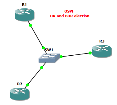
I have created a small Backbone area with three OSPF speaking routers. We can use this small scenario to see the election finished for the DR and the BDR. And also we can force our DR selection process. 


The configs are very simple. Every router has a Loopback IP, that is used as a ROUTER-ID in the OSPF domain. All the routers belong to the AREA 0 and have their connected networks associated to the area.

R1
interface Loopback0
 ip address 1.1.1.1 255.255.255.255
!
interface FastEthernet0/0
 ip address 172.16.1.1 255.255.255.0
 duplex auto
 speed auto
!
router ospf 1
 router-id 1.1.1.1
 log-adjacency-changes
 network 1.1.1.1 0.0.0.0 area 0
 network 172.16.1.0 0.0.0.255 area 0

R2
interface Loopback0
 ip address 2.2.2.2 255.255.255.255
!
interface FastEthernet0/0
 ip address 172.16.1.2 255.255.255.0
 duplex auto
 speed auto
!
router ospf 1
 router-id 2.2.2.2
 log-adjacency-changes
 network 2.2.2.2 0.0.0.0 area 0
 network 172.16.1.0 0.0.0.255 area 0

R3
interface Loopback0
 ip address 3.3.3.3 255.255.255.255
!
interface FastEthernet0/0
 ip address 172.16.1.3 255.255.255.0
 duplex auto
 speed auto
!
router ospf 1
 router-id 3.3.3.3
 log-adjacency-changes
 network 3.3.3.3 0.0.0.0 area 0
 network 172.16.1.0 0.0.0.255 area 0

To verify the DR and the BDR election , we can see the neighbor relationship on the R3. 

R3#sh ip ospf neighbor
Neighbor ID     Pri   State           Dead Time   Address         Interface
1.1.1.1           1   FULL/DR         00:00:36    172.16.1.1      FastEthernet0/0
2.2.2.2           1   FULL/BDR        00:00:32    172.16.1.2      FastEthernet0/0

As we can see , the default election OSPF mechanism used the lowest IP address to elect the DR in the broadcast domain we have created. We can also check the status of the OSPF interface and see the priority for the OSPF election process. 

R1#sh ip ospf interface fastEthernet 0/0
FastEthernet0/0 is up, line protocol is up
  Internet Address 172.16.1.1/24, Area 0
  Process ID 1, Router ID 1.1.1.1, Network Type BROADCAST, Cost: 1
  Transmit Delay is 1 sec, State DR, Priority 1
  Designated Router (ID) 1.1.1.1, Interface address 172.16.1.1
  Backup Designated router (ID) 2.2.2.2, Interface address 172.16.1.2
  Timer intervals configured, Hello 10, Dead 40, Wait 40, Retransmit 5
    oob-resync timeout 40
    Hello due in 00:00:02
  Supports Link-local Signaling (LLS)
  Index 2/2, flood queue length 0
  Next 0x0(0)/0x0(0)
  Last flood scan length is 1, maximum is 1
  Last flood scan time is 0 msec, maximum is 0 msec
  Neighbor Count is 2, Adjacent neighbor count is 2
    Adjacent with neighbor 2.2.2.2  (Backup Designated Router)
    Adjacent with neighbor 3.3.3.3
  Suppress hello for 0 neighbor(s)

We can see a lot from this output. By default the OSPF uses the Highest Priority number for the DR election, and if every router in the BROADCAST network has the same, the the tie breaker is the lowest router-id.

Now we should change the topology. Say the the R3 has higher CPU resoruces and NVRAM capabalities, we will for the OSPF protocol to elect the R3 to become the Designated router for our broadcast network. This is done via a simple command on the interfaces that are responsible for the OSPF Hello packet sending, in our case the F0/0.

R1
R1(config)#interface fastEthernet 0/0
R1(config-if)#ip ospf priority 0
!
R1#clear ip ospf process
Reset ALL OSPF processes? [no]: y

R2
R2(config)#interface fastEthernet 0/0
R2(config-if)#ip ospf priority 0
!
R2#clear ip ospf process
Reset ALL OSPF processes? [no]: y

We have disabled the possibility for the R1 and R2 to become the DR router. After a couple of second we will setup the new , higher priority on the routers, that will force the R3 to become the DR, inspite of the highest router-id.

R1
R1(config)#interface fastEthernet 0/0
R1(config-if)#ip ospf priority 254
!
R1#clear ip ospf process
Reset ALL OSPF processes? [no]: y

R2
R2(config)#interface fastEthernet 0/0
R2(config-if)#ip ospf priority 255
!
R2#clear ip ospf process
Reset ALL OSPF processes? [no]: y

Now to verify the final output. 

R1#sh ip ospf neighbor
Neighbor ID     Pri   State           Dead Time   Address         Interface
2.2.2.2         255   FULL/BDR        00:00:33    172.16.1.2      FastEthernet0/0
3.3.3.3           1   FULL/DR         00:00:37    172.16.1.3      FastEthernet0/0

We can now see that the R3 is the Designated router for the 172.16.1.0/24 subnet and the R2 has been relected as the Backup Designated router.
This is all to it.

Feel free to comment.

Saturday, September 7, 2013

OSPF MD5 Authentification

Configure OSPF MD5 authentification


OSPF protocol relies on  the SPF algorhythm to calculate the changes in the LSA database, propagate LSA packets end form neighbor communication (as many other functions). OSPF is a great IGP in many scenarios, but the packets between the routers and firewalls can be intercepted and spoofed. This can be easily done , to mitigate a DDOS attack on a OSPF speaking router. 
I have configured two OSPF speaking routers to use the MD5 authentification in their backbone area. 


The basic configs to form the AREA 0 connectivity follows:

R1
interface Loopback0
 ip address 1.1.1.1 255.255.255.0
!
interface FastEthernet0/0
 ip address 192.168.1.1 255.255.255.252
 duplex auto
 speed auto
!
router ospf 1
 log-adjacency-changes
 network 0.0.0.0 255.255.255.255 area 0

R2
interface Loopback0
 ip address 2.2.2.2 255.255.255.255
!
interface FastEthernet0/0
 ip address 192.168.1.2 255.255.255.252
 duplex auto
 speed auto
!
router ospf 1
 log-adjacency-changes
 network 0.0.0.0 255.255.255.255 area 0

Now let us configure the MD5 Authentification on the Backbone Area. Notice that every router must use the MD5 encryption. If not that router cannot be apart of the Area 0.

R1
R1(config-router)#area 0 authentication message-digest
R1(config)#interface fastEthernet 0/0
R1(config-if)#ip ospf message-digest-key 1 md5 cisco

R2
R2(config-router)#area 0 authentication message-digest
R2(config)#interface fastEthernet 0/0
R2(config-if)#ip ospf message-digest-key 1 md5 cisco


After entering the auth scripts the neighbors form a relationship once more.
%OSPF-5-ADJCHG: Process 1, Nbr 1.1.1.1 on FastEthernet0/0 from LOADING to FULL, Loading

The last thing that is left is to verify that the OSPF Hello and Update packets are authentificated trough the proper interfaces. This can be done on both routers. 

R1#sh ip ospf interface fastEthernet 0/0
FastEthernet0/0 is up, line protocol is up
  Internet Address 192.168.1.1/30, Area 0
  Process ID 1, Router ID 1.1.1.1, Network Type BROADCAST, Cost: 10
  Transmit Delay is 1 sec, State BDR, Priority 1
  Designated Router (ID) 2.2.2.2, Interface address 192.168.1.2
  Backup Designated router (ID) 1.1.1.1, Interface address 192.168.1.1
  Flush timer for old DR LSA due in 00:01:02
  Timer intervals configured, Hello 10, Dead 40, Wait 40, Retransmit 5
    oob-resync timeout 40
    Hello due in 00:00:05
  Supports Link-local Signaling (LLS)
  Cisco NSF helper support enabled
  IETF NSF helper support enabled
  Index 1/1, flood queue length 0
  Next 0x0(0)/0x0(0)
  Last flood scan length is 1, maximum is 1
  Last flood scan time is 0 msec, maximum is 0 msec
  Neighbor Count is 1, Adjacent neighbor count is 1
    Adjacent with neighbor 2.2.2.2  (Designated Router)
  Suppress hello for 0 neighbor(s)
  Message digest authentication enabled
    Youngest key id is 1

We can see that we have succesfull key exchange now. We can further debug the adjancacies between the routers using the debug ip ospf adj. This is very helpful to see if the OSPF speaking routers will not form the neighbor relationship again.

Fell free to comment.

Friday, September 6, 2013

Implement DHCP Snooping - rogue prevention

Why we need to secure an Enterprise DHCP server ?


DHCP snooping is a security feature that acts like a firewall between untrusted hosts and trusted DHCP servers. The fundamental use case for DHCP snooping is to prevent unauthorized (rogue) DHCP servers offering IP addresses to DHCP clients. Rogue DHCP servers are often used in man in the middle or denial of service attacks for malicious purposes. However, the most common DoS scenario is that of an end-user plugging in a consumer-grade router at their desk, ignorant that the device they plugged in is a DHCP server by default.

DHCP snooping will drop DHCP messages from a DHCP server that is not trusted. Trusted DHCP servers are identified by configuring a switchport’s DHCP snooping trust state. DHCP server messages can flow through switchports that have a DHCP snooping trusted state. DHCP server messages will be dropped if attempting to flow through a switchport that is not trusted.

Now let us look at a small diagram I have created with a snooping switch and a DHCP L3 switch, with a rogue DHCP server inside the network.


First we should configure the snooping option on the global config via the Snooper switch CLI.

SNOOPER(config)#ip dhcp snooping

I have created a VLAN 100 , so we must enable DHCP packet snooping for this VLAN.

SNOOPER(config)#ip dhcp snooping vlan 100

Then we must setup trusted interface between the SNOOPER and the DHCP Server. This is a trunk interface configured to traverse all VLANs.

SNOOPER(config)#int fa0/11
SNOOPER(config-if)#ip dhcp snooping trust

This is all on can do for a simple DHCP SNOOPING option. This will prevent the ROGUE DHCP server to traverse DHCP packets to the VLAN100 and confuse the client PC.

More options one can set, in a more complex scenario can be bound found at this link.

Thanks.

Wednesday, September 4, 2013

DDOS attack mitigation via remote black hole

How to black hole (stop) an attacker inside your network

Remote triggered Black Hole filtering and preventing of spoofed, DDOS active subnets is a great way to save router resources and prevent the attacker from damaging your network. 
A common DoS attack directed against a customer of a service provider involves generating a greater volume of attack traffic destined for the target than will fit down the links from the service provider(s) to the victim (customer). This traffic "starves out" legitimate traffic and often results in collateral damage or negative effects to other customers or the network infrastructure as well.  Rather than having all destinations on their network be affected by the attack, the customer may ask their service provider to filter traffic destined to the target destination IP address(es), or the service provider may determine that this is necessary themselves, in order to preserve network availability.
However, with destination-based RTBH filtering, the impact of the attack on the target is complete.  That is, destination-based RTBH filtering injects a discard route into the forwarding table for the target prefix.  All packets towards that destination, attack traffic AND legitimate traffic, are then dropped by the participating routers, thereby taking the target completely offline.  The benefit is  that collateral damage to other systems or network availability at the customer location or in the ISP network is limited, but the negative impact to the target itself is arguably increased.
In this small scenario I will use a eBGP speaking router that will advertise the "spoofed DDOS subnet" of 99.99.99.0/24. All of the iBGP routers inside the AS100 domain will have this prefix installed in the BGP table. 

The iBGP router CX2 is used as a trigger device, that has a simple task, to advertise the DDOS prefix inside the AS100, 
and put those packets inside the Black Hole. Let us use the configuration of the Trigger router.
CX2
interface Loopback1 ip address 192.0.2.1 255.255.255.255
!
route-map BLACK-HOLE permit 10 match tag 999 set local-preference 200 set origin igp set community no-export set ip next-hop 192.0.2.1 ! route-map BLACK-HOLE deny 20
!
router bgp 100 no synchronization bgp log-neighbor-changes network 5.5.5.5 mask 255.255.255.255 redistribute static route-map BLACK-HOLE neighbor 16.2.1.1 remote-as 100 neighbor 18.1.1.2 remote-as 100 no auto-summary
We have created a simple route map that will tagg the static route of our given prefix and set the next hop towards the 192.0.2.1 interface. 
This address belongs to the discard address space. Every other iBGP router must have a 
static route for the 192.0.2.1 address that points those packets to the NULL0 interface.
CX1#ip route 192.0.2.1 255.255.255.255 Null0
Customer#ip route 192.0.2.1 255.255.255.255 Null0
Now let us take a look at the BGP table of the CX1 router. We can see the 99.99.99.0 prefix is being advertised 
into the table and we have connectivity with the SPOOFED address.
CX1#sh ip bgp 99.99.99.0 BGP routing table entry for 99.99.99.0/24, version 18 Paths: (1 available, best #1, table Default-IP-Routing-Table) Not advertised to any peer 200 65535 16.1.1.2 from 16.1.1.2 (1.1.1.1) Origin IGP, metric 0, localpref 100, valid, internal, best
We can test the route by pinging the spoofed address.
CX1#ping 99.99.99.1 source loopback 0 Type escape sequence to abort. Sending 5, 100-byte ICMP Echos to 99.99.99.1, timeout is 2 seconds: Packet sent with a source address of 4.4.4.4 !!!!! Success rate is 100 percent (5/5), round-trip min/avg/max = 48/74/96 ms
Now to deny this traffic trough the AS100 we must redistribute and create a static route on the 
trigger router 
that will be distributed inside the AS100. I will let a long ping period from the CX1 router to 
demonstrate how the traffic stops inside the AS100 as soon as I create the static route for the 99.99.99.0/24 subnet.
As soon as I typed in the static route the PING has stopped. And if we look at the BGP table of 
the CX1 router now, we can se that the route is being advertised from the TRIGGER router
, and the next-hop is set to the 192.0.2.1 , the discard IP address.

CX1#sh ip route 99.99.99.0
Routing entry for 99.99.99.0/24
  Known via "bgp 100", distance 200, metric 0, type internal
  Last update from 192.0.2.1 00:02:23 ago
  Routing Descriptor Blocks:
  * 192.0.2.1, from 16.2.1.2, 00:02:23 ago
      Route metric is 0, traffic share count is 1
      AS Hops 0

This very simple DDOS mechanism can be used in more complex scenarios, with redundant Route Reflectors inside a large BGP domain. 
One can stop an attacker in a very short time 
period. There are more explanations on the RFC5635 document.

Feel free to comment.

Monday, September 2, 2013

BGP Communities - routes reside inside the local AS

Setting the NO-EXPORT BGP community 

BGP communities are attributes that maybe added to every prefix we choose. This is very interesting if one wants to logically separate incoming and outgoing traffic. With communities we have more granular control over the data plane inside our Autonomus system. 
The communities attribute is a way to group destinations into communities and apply routing decisions based on the communities. This method simplifies the configuration of a BGP speaker that controls distribution of routing information.
The communities attribute is an optional, transitive, global attribute in the numerical range from 1 to 4,294,967,200. Along with Internet community, there are a few predefined, well-known communities, as follows:
  • internet—Advertise this route to the Internet community. All routers belong to it.
  • no-export—Do not advertise this route to eBGP peers.
  • no-advertise—Do not advertise this route to any peer (internal or external).
  • local-as—Do not advertise this route to peers outside the local autonomous system. This route will not be advertised to other autonomous systems or sub-autonomous systems when confederations are configured.

In this small case scenario we have a customer AS 100 that does not want some prefixes to be advertised outside his own AS. Maybe the prefixes are malicious, or they have no agreement with the ISP companies or within any other reason this can be done with using the BGP default community NO-EXPORT. Let us take a look into the diagram.


In our small example we will be looking at the CX1 router and some of the ISP routing tables. First let us take a look at the BGP configs of the CX1 router, and the BGP table of the ISP2 router.


We can see that the ISP2 router has the two prefixes inside the RIB table. Those the prefixes we do not want to advertise outside the AS100. This is achieved via a simple route-map and an ACL that is associated with the desired traffic.

CX1#sh ip access-lists
Standard IP access list 1
    10 permit 44.44.44.0, wildcard bits 0.0.1.255 (2 matches)

CX1#sh route-map
route-map NO-EXPORT, permit, sequence 10
  Match clauses:
    ip address (access-lists): 1
  Set clauses:
    community no-export
  Policy routing matches: 0 packets, 0 bytes

CX1
neighbor 16.1.1.2 send-community both
 neighbor 16.1.1.2 route-map NO-EXPORT out

We have an ACL that is used to capture source of loopback address advertised with the prefixes 44.44.44.0/24 and 44.44.45.0/24. After that I have created an route-map called NO-EXPORT that uses the acl 1 and sets the community no-export on those prefixes. Then we have applied this route map to the neighbor inside the AS100.
Now let us see the RIB table of the ISP2 router.


And it is working fine, we do not see the prefixes we stopped to advertise. We can verify this further on the edge router of the AS100. 

CUSTOMER#sh ip bgp neighbors 172.16.1.2 advertised-routes
BGP table version is 11, local router ID is 1.1.1.1
Status codes: s suppressed, d damped, h history, * valid, > best, i - internal,
              r RIB-failure, S Stale
Origin codes: i - IGP, e - EGP, ? - incomplete

   Network          Next Hop            Metric LocPrf Weight Path
*> 1.1.1.1/32       0.0.0.0                  0         32768 i
*> 2.2.2.2/32       192.168.1.2              0             0 200 i
*> 3.3.3.3/32       172.16.1.2               0             0 300 i
*>i5.5.5.5/32       17.1.1.2                 0    100      0 i

We can see that the prefixes are not being advertised to the eBGP neighbor as we intended. Down following we can see the BGP table of the AS100 edge router.

Total number of prefixes 4

CUSTOMER#sh ip bgp 44.44.44.0
BGP routing table entry for 44.44.44.0/24, version 10
Paths: (1 available, best #1, table Default-IP-Routing-Table, not advertised to EBGP peer)
  Not advertised to any peer
  Local
    16.1.1.1 from 16.1.1.1 (4.4.4.4)
      Origin IGP, metric 0, localpref 100, valid, internal, best
      Community: no-export

The prefix 44.44.44.0 is in the routing table but it has the no-export community attached to the route. Thus the prefix is not being exported to the eBGP neighbors. Very simple and clean.

Feel free to comment.

Influence routing with BGP AS-Path prepend

Inbound traffic control with BGP prepending


Border Gateway Protocol has a rich set of attributes and combines them with built in algorithm to detect and install the best path to a certain NLRI. I will explain in further blogs how BGP uses the Best Path Selection algorithm to install the best path into to the table. In this particular scenario the tiebraker is the shortest AS Path. When a router sees a route with two BGP AS paths it will install the route with the shortest one in the table. This BGP feature can be used to influence how traffic flows into the Autonomous system. 
I have created a small scenario with 3 eBGP speaking routers. The customer is multi-homing two links towards the ISP cloud, and we will manipulate how the inbound traffic will flow (which links will be used).

Every eBGP router will be configured to advertise the loopback IP address via BGP. After the initial configs we will look at the BGP table of the ISPs and the Customer router.

CUSTOMER
interface Loopback0
 ip address 1.1.1.1 255.255.255.255
!
interface Serial0/0
 ip address 192.168.1.1 255.255.255.252
 serial restart-delay 0
!
interface Ethernet1/0
 ip address 172.16.1.1 255.255.255.252
 half-duplex
!
router bgp 100
 no synchronization
 bgp router-id 1.1.1.1
 bgp log-neighbor-changes
 network 1.1.1.1 mask 255.255.255.255
 neighbor 172.16.1.2 remote-as 300
 neighbor 192.168.1.2 remote-as 200
 no auto-summary

ISP1
interface Loopback0
 ip address 2.2.2.2 255.255.255.255
!
interface Serial0/0
 ip address 192.168.1.2 255.255.255.252
 serial restart-delay 0
!
interface Ethernet1/0
 ip address 10.0.0.1 255.255.255.252
 half-duplex
!
router bgp 200
 no synchronization
 bgp router-id 2.2.2.2
 bgp log-neighbor-changes
 network 2.2.2.2 mask 255.255.255.255
 neighbor 10.0.0.2 remote-as 300
 neighbor 192.168.1.1 remote-as 100
 no auto-summary

ISP2
interface Loopback0
 ip address 3.3.3.3 255.255.255.255
!
interface Ethernet0/0
 ip address 10.0.0.2 255.255.255.252
 half-duplex
!
interface Ethernet0/1
 ip address 172.16.1.2 255.255.255.252
 half-duplex
!
router bgp 300
 no synchronization
 bgp router-id 3.3.3.3
 bgp log-neighbor-changes
 network 3.3.3.3 mask 255.255.255.255
 neighbor 10.0.0.1 remote-as 200
 neighbor 172.16.1.1 remote-as 100
 no auto-summary

We can inspect now the RIB of the ISP1 router. To reach the 1.1.1.1 prefix to the customer router it will use the shortest path via the Serial WAN link.

ISP1#sh ip bgp 1.1.1.1
BGP routing table entry for 1.1.1.1/32, version 3
Paths: (2 available, best #2, table Default-IP-Routing-Table)
  Advertised to update-groups:
     1
  300 100
    10.0.0.2 from 10.0.0.2 (3.3.3.3)
      Origin IGP, localpref 100, valid, external
  100
    192.168.1.1 from 192.168.1.1 (1.1.1.1)
      Origin IGP, metric 0, localpref 100, valid, external, best

As we can see the shortest AS path with only on AS Hop (100) is used to get to the prefix 1.1.1.1/32. As this is the best path the traceroute from the ISP1 router to the CUSTOMER networks will also follow the Serial WAN link. 

ISP1#traceroute 1.1.1.1 source loopback 0
Type escape sequence to abort.
Tracing the route to 1.1.1.1
  1 192.168.1.2 44 msec 20 msec 16 msec


If one should prefer the faster Ethernet WAN link via the ISP2 router we should create a ROUTE-MAP that will prepend our AS 100 several time, so after that the Serial WAN link should not be considered best after that.

CUSTOMER#sh route-map
route-map PREPEND, permit, sequence 10
  Match clauses:
  Set clauses:
    as-path prepend 100 100 100 100
  Policy routing matches: 0 packets, 0 bytes

The traffic that is going to be prepended with several AS100 paths in the vector is going to be filtered via the neighbor statement under the BGP Process.

CUSTOMER(config-router)#neighbor 192.168.1.2 route-map PREPEND out

To take effect we should use the Route Refresh BGP feature.

CUSTOMER#clear ip bgp 192.168.1.2 soft

Now we can see a change in the BGP RIB of the ISP1 router. The Serial WAN link is no more preffered as the best path for the 1.1.1.1 prefix. So now ISP1 reaches the Customer router via the ISP2 link. 

ISP1#sh ip bgp 1.1.1.1
BGP routing table entry for 1.1.1.1/32, version 6
Paths: (2 available, best #1, table Default-IP-Routing-Table)
Flag: 0x820
  Advertised to update-groups:
     1
  300 100
    10.0.0.2 from 10.0.0.2 (3.3.3.3)
      Origin IGP, localpref 100, valid, external, best
  100 100 100 100 100
    192.168.1.1 from 192.168.1.1 (1.1.1.1)
      Origin IGP, metric 0, localpref 100, valid, external

If we do another traceroute , we will see that the preffered path to reach the CUSTOMER subnets, is via the Ethernet WAN link , towards the ISP2. All of the inbound traffic towards the CUSTOMER is now rerouted to this link. 

ISP1#traceroute 1.1.1.1 source loopback 0
Type escape sequence to abort.
Tracing the route to 1.1.1.1
  1 10.0.0.2 44 msec 20 msec 16 msec
  2 172.16.1.1 60 msec *  28 msec

We have achieved also a small redundancy here, because we can still reach some subnets from the ISP1 via the Serial Link, but all of the inbound traffic is now utilizied over the Ethernet Link, that is faster.

Feel free to comment.